


ix AIMB-210 User Manual
Contents
Chapter 1 General Information ............................1
1.1 Introduction ............................................................................................... 2
1.2 Features .................................................................................................... 2
1.3 Specifications ............................................................................................ 3
1.3.1 System .......................................................................................... 3
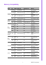
1.3.2 Memory......................................................................................... 3
1.3.3 Input/Output .................................................................................. 3
1.3.4 Graphics........................................................................................ 3
1.3.5 Ethernet LAN ................................................................................ 3
1.3.6 Industrial features ......................................................................... 4
1.3.7 Mechanical and environmental specifications............................... 4
1.4 Jumpers and Connectors.......................................................................... 4
Table 1.1: Jumpers...................................................................... 4
Table 1.2: Connectors ................................................................. 4
1.5 Board layout: Jumper and Connector Locations ....................................... 6
Figure 1.1 Jumper and Connector Location ................................ 6
Figure 1.2 I/O Connectors ........................................................... 6
1.6 AIMB-210 Board Diagram ......................................................................... 7
Figure 1.3 AIMB-210 Board Diagram .......................................... 7
1.7 Safety Precautions .................................................................................... 8
1.8 Jumper Settings ........................................................................................ 9
1.8.1 How to Set Jumpers...................................................................... 9
1.8.2 CMOS Clear (CMOS1) ................................................................. 9
Table 1.3: CMOS1....................................................................... 9
1.8.3 COM2 RS 232/422/485 Mode Selector (JSETCOM2)................ 10
Table 1.4: COM2 RS 232/422/485 Mode Selector
(JSETCOM2)............................................................ 10
1.8.4 JLV1/JLV2: LCD Power 3.3 V/5 V Selector ................................ 10
Table 1.5: JLV1/JLV2: LCD Power 3.3 V/5 V Selector.............. 10
1.8.5 JPSON1: ATX, AT Mode Selector .............................................. 11
Table 1.6: JPSON1: ATX, AT Mode Selector............................ 11
1.8.6 JWDT1: Watchdog Timer Output Option .................................... 11
Table 1.7: JWDT1: Watchdog Timer Output Option.................. 11
1.9 System Memory ...................................................................................... 12
1.10 Memory Installation Procedures.............................................................. 12
Chapter 2 Connecting Peripherals ....................13
2.1 Introduction ............................................................................................. 14
2.2 Parallel Port (LPT1)................................................................................. 14
2.3 Primary (IDE1) IDE Connector................................................................ 15
2.4 USB Ports (LAN1_USB12/LAN2_USB34/USB56/USB78) ..................... 16
Table 2.1: LAN LED Indicator.................................................... 16
2.5 TV-Out Connector (TVOUT1) ................................................................. 17
Table 2.2: TV-Out Connector (TVOUT1)................................... 17
2.6 VGA Connector (VGA1).......................................................................... 18
2.7 Serial Ports (COM1~COM6) ................................................................... 19
2.8 PS/2 Keyboard and Mouse Connector (KBMS1) .................................... 20
2.9 CPU Fan Connector (CPU_FAN1).......................................................... 21
2.10 System FAN Connector (CHA_FAN1) .................................................... 22
2.11 Front Panel Connectors (JFP1/JFP2/JFP3)............................................ 23
2.11.1 ATX soft power switch (JFP1 / PWR_SW) ................................ 23
2.11.2 Reset (JFP1 / RESET)................................................................ 23
2.11.3 HDD LED (JFP2 / HDDLED)....................................................... 23