


23 AIMB-221 User Manual
Chapter 2 Connecting Peripherals
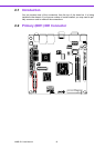
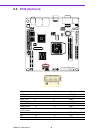
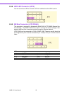
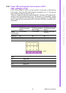
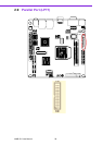
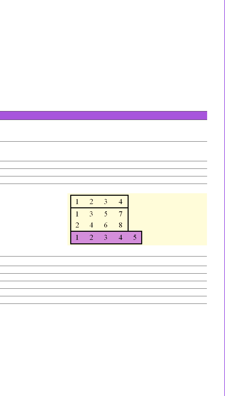
2.4.6 Power LED and keyboard lock connector (JFP3 /
PWR_LED&KEY LOCK)
(JFP3 / PWR_LED&KEY LOCK) is a 5-pin connector for the power on LED and Key
Lock function. The Power LED cable should be connected to pin 1-3. The key lock
button cable should be connected to pin 4-5.
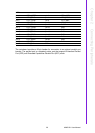
There are 3 modes for the power supply connection. The first is “ATX power mode”,
system is on/off by a tentative power button. The second is “AT Power Mode”, system
is on/off by the switch of the Power supply. The third is another “AT Power Mode”
which is using the front panel power switch. The power LED status is indicated as fol-
lowing table:
Table 2.1: ATX power supply LED status (No support for AT power)
Power Mode LED (ATX Power Mode)
(On/Off by tentative
button)
LED (AT Power Mode)
(On/Off by switching
power supply)
LED (AT Power Mode)
(On/Off by front panel
switch)
PSON1
(On Back plane)
Jumper Setting
2-3 pin closed 1-2 pin closed Connect 1-2 pin cable
with switch
System On On On On
System Status Fast flashes Fast flashes Fast flashes
System Off Slow flashes Off Off
JFP3
pin.1 PWR_LED+
pin.2 NC
pin.3 GND
pin.4 #KB_LOCK
pin.5 GND
JFP3