


vii AIMB-221 User Manual
Contents
Chapter 1 Hardware Configuration......................1
1.1 Introduction ............................................................................................... 2
1.2 Features .................................................................................................... 2
1.3 Specifications ............................................................................................ 3
1.3.1 System .......................................................................................... 3
1.3.2 Memory......................................................................................... 3
1.3.3 Input/Output .................................................................................. 4
1.3.4 Ethernet LAN ................................................................................ 4
1.3.5 Industrial features ......................................................................... 4
1.3.6 Mechanical and environmental specifications............................... 4
1.4 Jumpers and Connectors .......................................................................... 4
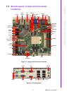
1.5 Board Layout: Jumper and Connector Locations...................................... 5
Figure 1.1 Jumper and Connector locations................................ 5
Figure 1.2 I/O connectors ............................................................ 5
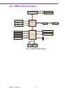
1.6 AIMB-221 Block Diagram.......................................................................... 6
Figure 1.3 AIMB-221 Block Diagram ........................................... 6
1.7 Jumpers and Connectors .......................................................................... 7
1.8 Safety Precautions .................................................................................... 8
1.9 Jumper Settings ........................................................................................ 8
1.9.1 How to set jumpers ....................................................................... 8
1.9.2 CMOS clear (JCMOS1) ................................................................ 9
Table 1.1: CMOS (JCMOS1)....................................................... 9
1.9.3 Watchdog timer output (JWDT1) .................................................. 9
Table 1.2: Watchdog timer output (JWDT1) ................................ 9
Table 1.3: ATX/AT mode selector (JPSON1) ............................ 10
Table 1.4: COM1 RS-232 with 5V or 12V selector (JSETCOM1) .
10
Table 1.5: COM2 RS-232/422/485 mode selector (JSETCOM2)..
10
Figure 1.4 COM2 RS-232/422/485 jumper setting .................... 10
1.10 System Memory ...................................................................................... 11
1.10.1 CPU FSB and memory speed..................................................... 11
1.11 Memory Installation Procedures.............................................................. 11
1.12 Cache Memory........................................................................................ 11
1.13 Processor Installation.............................................................................. 11
1.14 PCI Bus Routing Table............................................................................ 12
Table 1.6: PCI Bus Routing Table ............................................. 12
Table 1.7: PCI1 (Routing: AD31 / PCI_#INTF, #INTG, #INTH,
#INTE) ...................................................................... 12
Table 1.8: MINIPCI1 (Routing: AD28 / #INTE / #INTF) ............. 13
Chapter 2 Connecting Peripherals ....................15
2.1 Introduction ............................................................................................. 16
2.2 Primary (IDE1) IDE Connector................................................................ 16
2.3 DVI2 (Optional) ....................................................................................... 18
2.4 Front Panel Connectors (JFP1, JFP2, JFP3).......................................... 20
2.4.1 ATX Soft Power Switch (JFP1) ................................................... 21
2.4.2 Reset Connector (JFP1) ............................................................. 21
2.4.3 External Speaker (JFP2)............................................................. 21
2.4.4 HDD LED Connector (JFP2)....................................................... 22
2.4.5 SM Bus Connector (JFP2 PIN6,8) .............................................. 22
2.4.6 Power LED and keyboard lock connector (JFP3 /PWR_LED&KEY
LOCK) ......................................................................................... 23