


11 Chapter 1
1.6 Safety Precautions
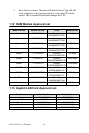
1.7 Jumper Settings
This section provides instructions on how to configure your card by set-
ting jumpers. It also includes the card's default settings and your options
for each jumper.
1.7.1 How to set jumpers
You configure your card to match the needs of your application by setting
jumpers. A jumper is a metal bridge that closes an electrical circuit. It
consists of two metal pins and a small metal clip (often protected by a
plastic cover) that slides over the pins to connect them. To “close” (or
turn ON) a jumper, you connect the pins with the clip. To “open” (or turn
OFF) a jumper, you remove the clip. Sometimes a jumper consists of a set
of three pins, labeled 1, 2, and 3. In this case you connect either pins 1
and 2, or 2 and 3.
A pair of needle-nose pliers may be useful when setting jumpers.
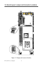
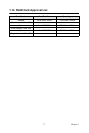
1.7.2 CMOS clear (J1)
The PCA-6185 CPU card contains a jumper that can erase CMOS data
and reset the system BIOS information. Normally this jumper should be
set with pins 1-2 closed. If you want to reset the CMOS data, set J1 to 2-3
Warning! Always completely disconnect the power cord
from your chassis whenever you work with the
hardware. Do not make connections while the
power is on. Sensitive electronic components
can be damaged by sudden power surges. Only
experienced electronics personnel should open
the PC chassis.
Caution! Always ground yourself to remove any static
charge before touching the CPU card. Modern
electronic devices are very sensitive to static
electric charges. As a safety precaution, use a
grounding wrist strap at all times. Place all elec-
tronic components in a static-dissipative surface
or static-shielded bag when they are not in the
chassis.