Chapter 1 General Information 47
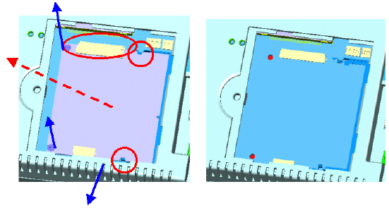
Step 4: The CPU board is now visible. It connects to the I/O board by a
144-pin SO-DIMM connector and a 50-pin FPC connector.
Step 5: Use a pair of tweezers to loosen the 50-pin FPC connector, and
release the FPC.
Step 6: Bend outward the two metal latches of the SO-DIMM connec
tor by thumbs. The free end of the CPU board would swing up.
Pull out the CPU board.
Figure 6.1-3 Remove the CPU board
Step 7: Insert a new CPU board to the SO-DIMM connector.
Step 8: Push down and lock the CPU board.
Step 9: Use a pair of tweezers to insert the 50-pin FPC to the connector
on the CPU board. Then tighten the connector.
Step 10: Replace the CPU board cover and fasten the screw.
Warning: The CPU cover is used as the cooling media of the
CPU. Thus it is usually of higher temperature than
other parts of the system. Be careful not to touch
this area without proper protection.


