


50
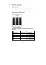
The active redundant parallel operation will switch
automatically to the increase power mode if more power is
required at the output of the UPS. This implements that the
redundancy level decreases or will diminish completely. On the
other hand the level of redundancy of the UPS will increase if
the power consumption on the output decreases.
The distribution generally is realised in the low voltage main
distribution (LVMD) where the external and the following sub
distribution for connected load circuits takes place. Such
parallel control panels in wall cabinets including an external HU
as well as input and output control panel can also be ordered
via AEG Power Supply System and their partners.
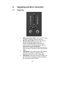
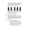
9.2 Setup / connection of the parallel operation field
The mains connection of each UPS is realised analogue to
the description in chapter 5.
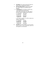
For the single phase mains connection for each
UPS the same phase has to be used, i.e. all
UPS have to use either L1 or L2 or L3 (no mix!).
The supply of the multi pole central external
manual bypass has to be realised with this
phase.
The UPS outlets are connected via separator with the parallel
operation bus-bar. At this point the instructions of chapter 5
are to follow.
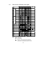
The following applies for output and input lines of the UPS:
The difference in length of the lines with a line length of up to
20 m may not vary more the 20% and with more than 20 m
not more than 10%.
The default bridge between “JP1” and “JP2” in the control
panel of every UPS has to be removed. The distribution of the
output has to be executed according the instructions of
chapter 5. Please take care of the exact labelling of the
elements to prevent any operation error. The communication
between the parallel connected units is realised with the 25
pole parallel operation line that comes with the UPS.