


CL4490 User’s Manual
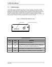
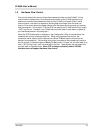
RS-232 Pin Assignments
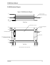
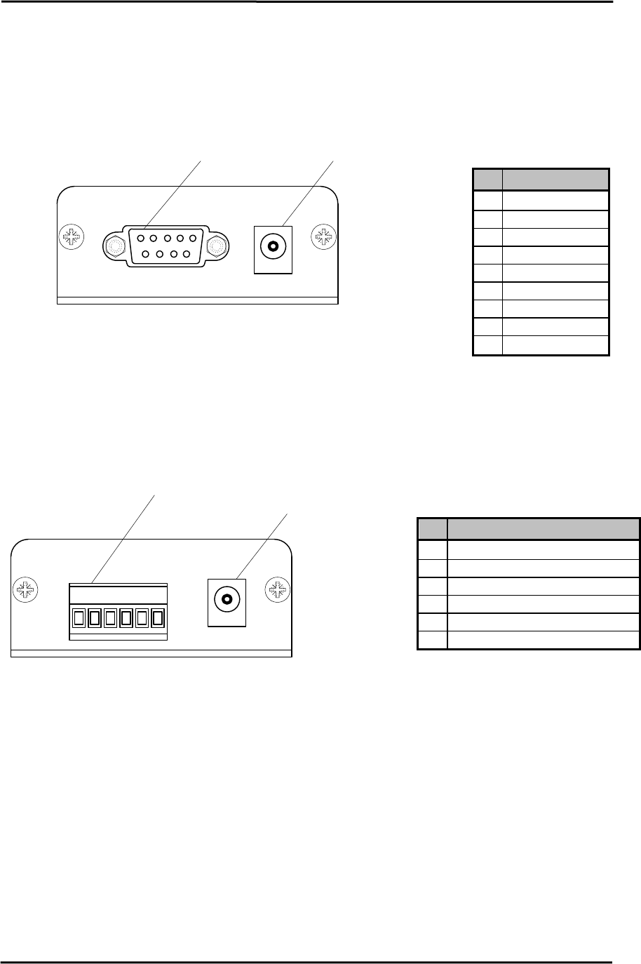
Figure 2- RS-232 CL4490 Back View
Power ConnectorDB9 Male Connector
15
69
Pin Description
NC
DCD
2 TxD
3 RxD
4 DSR
5 GND
6 DTR
7 CTS
8 RTS
NC
RI
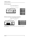
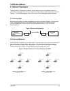
RS-485 (2-wire Half Duplex) Terminal Block Pin Assignments
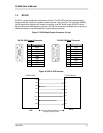
Figure 3- RS-485 CL4490 Back View
16
Power Connector
Terminal Block
Pin Description
1 VCC (6V-18V)(1.3 A
2 485-
(
485B
)
3 No Connect
4 No Connect
5 485+
(
485A
)
6GND
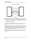
Note: Standard power is applied through the power connector. Alternative power is available via
the terminal block pins.
10/3/2005 8