


Installation
19
■ There must be no or minimal current flowing through the connector pins at the back of the module
that is being removed. This can be accomplished by disabling the module. If this precaution is
repeatedly violated at high current, the connector pins at the back of the module
will be damaged.
■ There must be no activity on the GPIB bus, the trigger connectors, or the FLT/INH connector of
the mainframe when a module is removed. This can be accomplished by not generating any GPIB
or FLT/INH activity, and by setting all modules to the trigger idle state (refer to the module
Programming Guide). If this precaution is violated, GPIB commands to other modules may be
corrupted, trigger or FLT/INH data may be lost, or an inadvertent trigger may be generated in
another module.
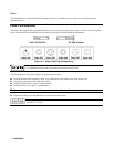
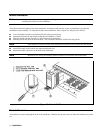
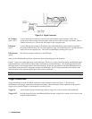
To remove the module from the mainframe, proceed as follows:
■ Use a flat-bladed screwdriver and release the pull tab by pressing down (see Figure 2-5).
■ Grasp the pull tab and pull the module out of the mainframe.
Note The module connector remains attached to the mainframe after the module has been removed.
Mainframe Turn-On Checkout
The turn-on checkout procedures that verify module operation also verify the operation of the MPS mainframe. You cannot
verify the operation of the mainframe without having at least one installed module. The module self-test sequence checks
the following mainframe functions:
■ mainframe microprocessor
■ GPIB interface
■ module/mainframe communications link
Refer to the module User’s Guide for complete information on the turn-on checkout procedure.