


Connections
22
Controller Connections
If you have only one MPS mainframe in your system, simply connect it to the controller using the GPIB cable. If you have
more than one mainframe, or if you also have an Agilent 667xA, 665xA, 664xA, or 603xA power supply in your system,
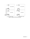
you can use the serial-link cable supplied with your mainframe to facilitate connections. Figure 3-2 illustrates the serial-link
connections.
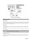
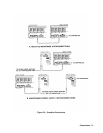
Multiple MPS Mainframes
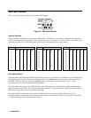
See Figure 3-2. Up to 16 modules may be controlled from a primary GPIB bus address by linking two mainframes.
■ The first mainframe in a linked configuration is directly connected to the controller via a GPIB cable. The frame mode
switch on the back of this mainframe is set to "MAIN". The first mainframe has a unique primary GPIB address and
the modules in this mainframe use secondary addresses (also referred to as subaddresses) 0 through 7.
■ The second or "linked" mainframe, connects to the first mainframe with the serial-link cable. The frame mode switch
on the back of this mainframe is set to "AUX". The second mainframe uses the same primary address as the first
mainframe, but the modules in the second mainframe use secondary addresses 8 through 15.
MPS Mainframe/Power Supply Connections
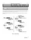
See Figure 3-2b. Only one mainframe can be serially linked to a system that includes Agilent 667xA, 665xA, 664xA, or
603xA power supplies. Because the mainframe has only one serial-link jack, it can be either linked at the beginning or at
the end of a power supply serial link system.
■ At the beginning of the serial link system, the mainframe is directly connected to the controller via the GPIB cable.
The frame mode switch on the back of this mainframe is set to "MAIN". The mainframe has a unique primary GPIB
address and the modules in this mainframe use secondary addresses (also referred to as subaddresses) 0 through 7. All
power supplies serially linked to the mainframe use the same primary GPIB address, but must use secondary addresses
8 through 15.
■ At the end of the serial link system, the mainframe is linked to the last power supply in the system with the serial-link
cable. The frame mode switch on the back of this mainframe is set to "AUX". The mainframe uses the same primary
GPIB address as the power supplies and the modules in this mainframe use secondary addresses 8 through 15. In this
configuration, you can have up to eight power supplies at secondary addresses 0 through 7 ahead of the mainframe.
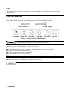
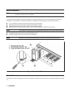
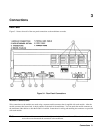
Keyboard Connection
The optional Agilent 66001A MPS Keyboard connects to the mainframe through the keyboard jack located at the front of
the mainframe and at the back of the mainframe as shown in Figure 3-1. More information on using the keyboard can be
found in the module User’s Guide.
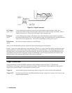
Digital Connections
A 4-pin connector and a quick-disconnect mating plug provide a discrete fault indicator (FLT) output and a remote inhibit
(INH) input (see Figure 3-3). Disconnect the mating plug to make your wire connections. The electrical characteristics of
the FLT output and the INH input are described in Chapter 1. More information on using digital connectors can be found in
Chapter 4 of the module User’s Guide under "RI Function" and "DFI Function".