


10
e. Press
.
f. Record the DMM and front panel display readings. DMM reading should be between 2.947V and 3.053V.
CR Mode Test
This test verifies that the module operates in the CR Mode and that the resistance programming is within specifications. The
programmed resistance values are checked by recording the voltage across the current monitor resistor and the input voltage
(voltage across the module’s input terminals), and then calculating the resistance value as follows:
Load resistance = Input voltage/(voltage across resistor/resistor value)
Note if the calculation significantly disagrees with the specified range of values, perform the CR MODE TEST
troubleshooting procedures in Figure 3-1 in Chapter 3 of the mainframe Service Manual. If the calculation is out of
tolerance, calibrate the applicable resistance range (see Chapter 6 in the Operating Manual).
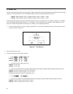
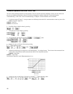
a. Connect the Electronic Load, power supply (Agilent 6032A or equivalent), and the 0.10 ohm current monitor resistor
as shown in Figure 2-1. Use the DMM to measure the voltage across the monitor resistor and across the module’s input
terminals.
b. Check the low ohm range as follows:
1. Press
, then
60501B:
;
.
60502B:
; .
2. Turn on power source and set for:
60501B: 15V and 5.5A.
60502B: 15V and 10.9A.
For the low ohm range test, the power supply will operate in the current limit mode.
3. Measure the voltage across the monitor resistor and across the module’s input terminals, then calculate the
Electronic Load resistance. The result should be between:
60501B: 1.868 and 1.931 ohms.
60502B: 0.984 and 1.016 ohms.
Note that the Electronic Load’s CR annunciator is on.
4. Then press:
60501B:
.
60502B:
.
5. Measure the voltage across the monitor resistor and across the module’s input terminals, then calculate the
Electronic Load resistance. The result should be between:
60501B: 0.0534 and 0.0866 ohms.
60502B: 0.0416 and 0.0584 ohms.