19
3
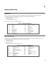
Replaceable Parts
Introduction
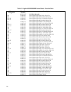
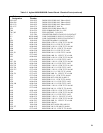
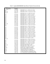
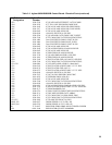
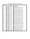
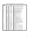
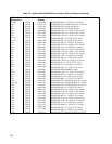
Tables 3-3 and 3-4 list the electrical components and Table 3-5 lists the mechanical components for the Agilent
60501B/60502B Electronic Load Modules. These tables provide the following information.
• Reference designation (see Table 3-1).
• Agilent part number.
• Description of part (see Table 3-2).
Refer to Figures 4-2 and 4-4 for component locations.
Table 3-1. Reference Designators
A Assembly RTB Removable Terminal Block
B Blower RTP Removable Jumper
C Capacitor S Switch
D Diode T Transformer
F Fuse TB Terminal Block
J Terminal Jack TBP Test Pin
MP Mechanical Part U Integrated Circuit
P Terminal Plug VR Voltage Regulator
Q Transistor W Cable Assembly
RT Thermal Resistor Y Oscillator
How To Order Parts
You can order parts from your local Agilent Technologies sales office (refer to the list at the end of this manual for the
office nearest you). When ordering parts, include the following information:
• Agilent part number.
• Description of the part.
• Quantity desired.
• Electronic Load model number (Agilent 60501B).
Table 3-2. Part Description Abbreviations
AL Aluminum PE Polyester
CC Carbon Composition PD Power Dissipation
CER Ceramic PP Polypropylene
DIP Dual In-Line Package PWR Power
DPDT Double Pole Double Throw RECT Rectifier
FF Flip Flop SIP Single In-Line Package
FXD Fixed TA Tantalum
GEN-PURP General Purpose TC Temperature Coefficient
IC Integrated Circuit TF Thin Film
MACH Machine W/ With
MO Meta1 Oxide


