


2-4 85032B/E
Specifications
Mechanical Characteristics
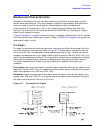
NOTE The gages for measuring type-N connectors compensate for the designed
offset of 5.26 mm (0.207 inch), therefore, protrusion and recession readings
are in relation to a zero reference plane (as if the inner and outer conductor
planes were intended to be flush). Gage readings can be directly compared
with the observed values listed in Table 2-2.
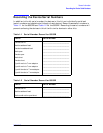
The pin depth value of each calibration device in this kit is not specified, but is an
important mechanical parameter. The electrical performance of the device depends, to
some extent, on its pin depth. The electrical specifications for each device in this kit take
into account the effect of pin depth on the device’s performance. Table 2-2 lists the typical
pin depths and measurement uncertainties, and provides observed pin depth limits for the
devices in the kit. If the pin depth of a device does not measure within the observed pin
depth limits, it may be an indication that the device fails to meet electrical specifications.
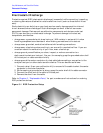
Refer to Figure 2-1 for an illustration of pin depth in type-N connectors.
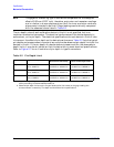
Table 2-2 Pin Depth Limit
Device Typical Pin Depth
Measurement Uncertainty
a
a. Approximately +2 sigma to −2 sigma of gage uncertainty based on studies done at the
factory according to recommended procedures.
Observed Pin Depth Limits
b
b. Observed pin depth limits are the range of observation limits seen on the gage reading due
to measurement uncertainty. The depth could still be within specifications.
Opens 0 to −0.0127 mm
0 to −0.0005 in
+0.0038 to −0.0038 mm
+0.00015 to −0.00015 in
+0.0038 to −0.0165 mm
+0.00015 to −0.00065 in
Shorts 0 to −0.0127 mm
0 to −0.0005 in
+0.0038 to −0.0038 mm
+0.00015 to −0.00015 in
+0.0038 to −0.0165 mm
+0.00015 to −0.00065 in
Fixed Loads 0 to −0.0508 mm
0 to −0.0020 in
+0.0038 to −0.0038 mm
+0.00015 to −0.00015 in
+0.0038 to −0.0546 mm
+0.00015 to −0.00215 in