


85032B/E 3-7
Use, Maintenance, and Care of the Devices
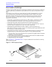
Gaging Connectors
When to Gage Connectors
Gage a connector at the following times:
• Prior to using a device for the first time: record the pin depth measurement so that it
can be compared with future readings. (It will serve as a good troubleshooting tool when
you suspect damage may have occurred to the device.)
• If either visual inspection or electrical performance suggests that the connector
interface may be out of typical range (due to wear or damage, for example).
• If a calibration device is used by someone else or on another system or piece of
equipment.
• Initially after every 100 connections, and after that as often as experience indicates.
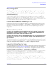
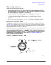
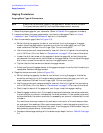
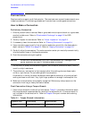
Reading the Connector Gage
The gage dial is divided into increments of 0.0001 inch and major divisions of 0.001 inch
(see Figure 3-2). For each revolution of the large dial, the smaller dial indicates a change of
0.01 inch. Use the small dial as the indicator of multiples of 0.01 inch. In most connector
measuring applications, this value will be zero.
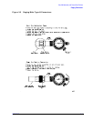
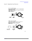
When making a measurement, the gage dial indicator will travel in one of two directions. If
the center conductor is recessed from the zero reference plane, the indicator will move
counterclockwise to indicate the amount of recession, which is read as a negative value. If
the center conductor protrudes, the indicator will move clockwise to indicate the amount of
protrusion, which is read as a positive value. Refer to “Pin Depth” on page 2-3 for
definitions of protrusion and recession.
Figure 3-2 Reading the Connector Gage