


3-8 85032B/E
Use, Maintenance, and Care of the Devices
Gaging Connectors
Gaging Procedures
Gaging Male Type-N Connectors
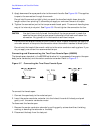
NOTE Always hold a connector gage by the gage barrel, below the dial indicator.
This gives the best stability, and improves measurement accuracy.
1. Select the proper gage for your connector. (Refer to Table 6-3 for gage part numbers).
2. Inspect and clean the gage, gage master, and device to be gaged. Refer to “Visual
Inspection” and “Cleaning Connectors” earlier in this chapter.
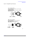
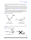
3. Zero the connector gage (refer to Figure 3-3):
a. While holding the gage by the barrel, and without turning the gage or the gage
master, screw the gage master connecting nut onto the male gage, just until you
meet resistance. Connect the nut finger tight. Do not overtighten.
b. Use the torque wrench recommended for use with this kit to tighten the connecting
nut to 135 N-cm (12 in-lb). Refer to “Connections” on page 3-12 for more information.
c. Loosen the dial lock screw on the gage and rotate the gage dial so that the pointer
corresponds to the correction value noted on the gage master. Do not adjust the gage
dial to zero, unless the correction value on the gage master is zero.
d. Tighten the dial lock screw and remove the gage master.
e. Attach and torque the gage master to the gage once again to verify that the setting is
repeatable. Remove the gage master.
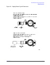
4. Gage the device connector (refer to Figure 3-3):
a. While holding the gage by the barrel, and without turning the gage or the device,
screw the connecting nut of the device being measured onto the gage, just until you
meet resistance. Connect the nut finger-tight. Do not overtighten.
b. Use the torque wrench recommended for use with this kit to tighten the connecting
nut to 135 N-cm (12 in-lb). Refer to “Connections” on page 3-12 for more information.
c. Gently tap the barrel of the gage with your finger to settle the gage reading.
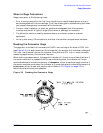
d. Read the gage indicator dial. If the needle has moved clockwise, the center conductor
is protruding by an amount indicated by the black
numbers. If the needle has moved
counterclockwise, the center conductor is recessed by an amount indicated by the red
numbers.
For maximum accuracy, measure the connector a minimum of three times and take
an average of the readings. After each measurement, rotate the gage a quarter-turn
to reduce measurement variations that result from the gage or the connector face not
being exactly perpendicular to the center axis.
e. Compare the average reading with the observed pin depth limits in Table 2-2 on page
2-4.