


3-12 85032B/E
Use, Maintenance, and Care of the Devices
Connections
Connections
Good connections require a skilled operator. The most common cause of measurement error
is bad connections. The following procedures illustrate how to make good connections.
How to Make a Connection
Preliminary Connection
1. Ground yourself and all devices. Wear a grounded wrist strap and work on a grounded,
conductive table mat. Refer to “Electrostatic Discharge” on page 3-2 for ESD
precautions.
2. Visually inspect the connectors. Refer to “Visual Inspection” on page 3-3.
3. If necessary, clean the connectors. Refer to “Cleaning Connectors” on page 3-4.
4. Use a connector gage to verify that all center conductors are within the observed pin
depth values in Table 2-2 on page 2-4. Refer to “Gaging Connectors” on page 3-6.
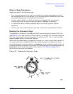
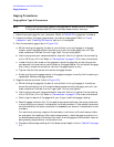
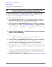
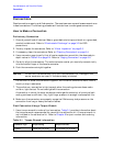
5. Carefully align the connectors. The male connector center pin must slip concentrically
into the contact finger of the female connector.
6. Push the connectors straight together.
CAUTION Do not turn the device body. Only turn the connector nut. Damage to the
center conductor can occur if the device body is twisted.
Do not twist or screw the connectors together. As the center conductors mate, there is
usually a slight resistance.
7. The preliminary connection is tight enough when the mating plane surfaces make
uniform, light contact. Do not overtighten this connection.
A connection in which the outer conductors make gentle contact at all points on both
mating surfaces is sufficient. Very light finger pressure is enough to accomplish this.
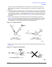
8. Make sure the connectors are properly supported. Relieve any side pressure on the
connection from long or heavy devices or cables.
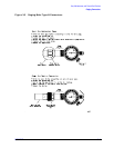
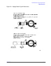
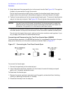
Final Connection Using a Torque Wrench
1. Use a torque wrench to make a final connection. Table 3-1 provides information about
the torque wrench recommended for use with this calibration kit. A torque wrench is
not included in the calibration kit. Refer to Chapter 6 for part number and ordering
information.
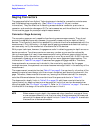
Table 3-1 Torque Wrench Information
Connector Type Torque Setting Torque Tolerance
Type-N 135 N-cm (12 in-lb) ±13.5 N-cm (±1.2 in-lb)