


4-8 Agilent B2200 User’s Guide, Edition 2
Programming
Programming Examples
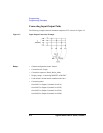
Connecting Input-Output Paths
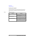
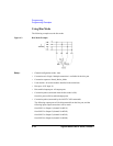
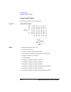
The following example connects instrument output to DUT as shown in Figure 4-2.
Figure 4-2 Input-Output Connection Example
Setup: • Channel configuration mode: Normal
• Connection rule: Single
• Connection sequence: Break_Before_Make
• Display strings: “Connecting MOSFET AG002201”
• Used module: Switch module installed in the slot 1.
• Connection paths:
from SMU1 to Output 1 (channel list 10101)
from SMU2 to Output 2 (channel list 10202)
from SMU3 to Output 3 (channel list 10303)
from SMU4 to Output 4 (channel list 10404)