


3-24 Agilent B2200 User’s Guide, Edition 2
Front Panel Operation
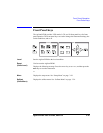
Display Functions
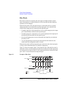
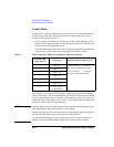
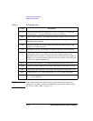
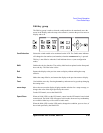
Table 3-5 LCD Display Items
NOTE In the remote mode and the default setting, only the Remote, Lock, and Error
indicators are available. To display all information, set the RMT_DSPL function
ON. Refer to “RMT_DSPL” on page 3-33.
Label Description
01 to 14 Port function assigned to the input ports 1 to 14. B (bias port), C (couple port),
G (ground port), - (ground enabled port), or blank (no function).
Shift Shift key status indicator. The triangle mark appears when the sub key is active.
Remote Remote status indicator. The triangle mark appears when the Agilent B2200 is in
the GPIB remote condition.
Lock Key status indicator. The triangle mark appears when the front panel keys are
locked by an external computer.
Error Error status indicator. The triangle mark appears when any error has occurred.
Card# Slot number of the switch module to be monitored. Displays A when the channel
configuration mode is Auto. In the auto mode, the modules installed in the
mainframe from slot number 1 continuously will be controlled as one module. Or
displays 1 to 4 when the channel configuration mode is Normal. The module can
be selected by the
Card Selection key.
Bias Bias mode status indicator. The triangle mark appears when the mode is ON.
Couple Couple mode status indicator. The triangle mark appears when the mode is ON.
Gnd Ground mode status indicator. The triangle mark appears when the mode is ON.
Rule Connection rule, FREE (plural route mode) or SINGLE (single route mode).
Sequence Connection sequence, BBM (Break Before Make), MBBR (Make Before Break), or
NO_SEQ (No Sequence).