Parity On
No Wait
No Idle
State
ON
1 2 3 4
Parity On
No Wait
No Idle
TD0-TD1
State
Timing
FuturePlus
Systems
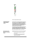
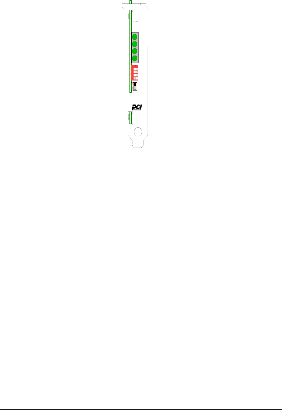
PCI Active Analysis Probe front panel
Powering the PCI
Active Analysis
Probe
The active circuitry on the PCI Active Analysis Probe module
gets its power from the logic analyzer PODs. No power is taken
from the target PCI system. Please Note: If the Analysis
Probe is plugged into the PCI bus and the logic analyzer is
not connected or powered up the input buffers on the
Analysis Probe will create a low impedance path to ground
thus inhibiting the PCI local bus and any card in the
extender card connector from working.
The Logic analyzer must be connected and powered on for
the PCI Active Analysis Probe to work properly. ONLY
connect to the analysis probe headers 7-10 if you are doing
64 bit analysis. Latchup may occur on the 64 bit interface
parts if they are powered on and not on a 64 bit bus.
The following explains how to connect the logic analyzer to the
PCI Active Analysis Probe for either state or timing analysis:
Connecting to the
PCI Active Analysis
Probe
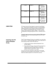
1. Remove the probe tip assemblies from the logic
analyzer cables.
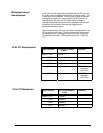
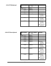
2. Plug the logic analyzer cables into the PCI Active
Analysis Probe cable headers as shown in the
appropriate following tables.
11


