


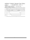
The PCI Active Analysis Probe module monitors signals for both
state and timing analysis. The below figure displays how the
cable headers are numbered.
Signal Connections
39 37 35 33 31 29 27 25 23 21 19 17 15 13 11 9 7 5 3 1
40 38 36 34 32 30 28 26 24 22 20 18 16 14 12 10 8 6 4 2
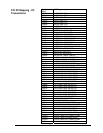
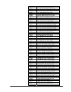
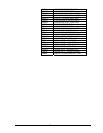
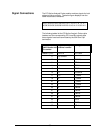
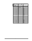
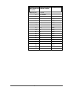
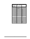
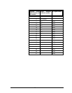
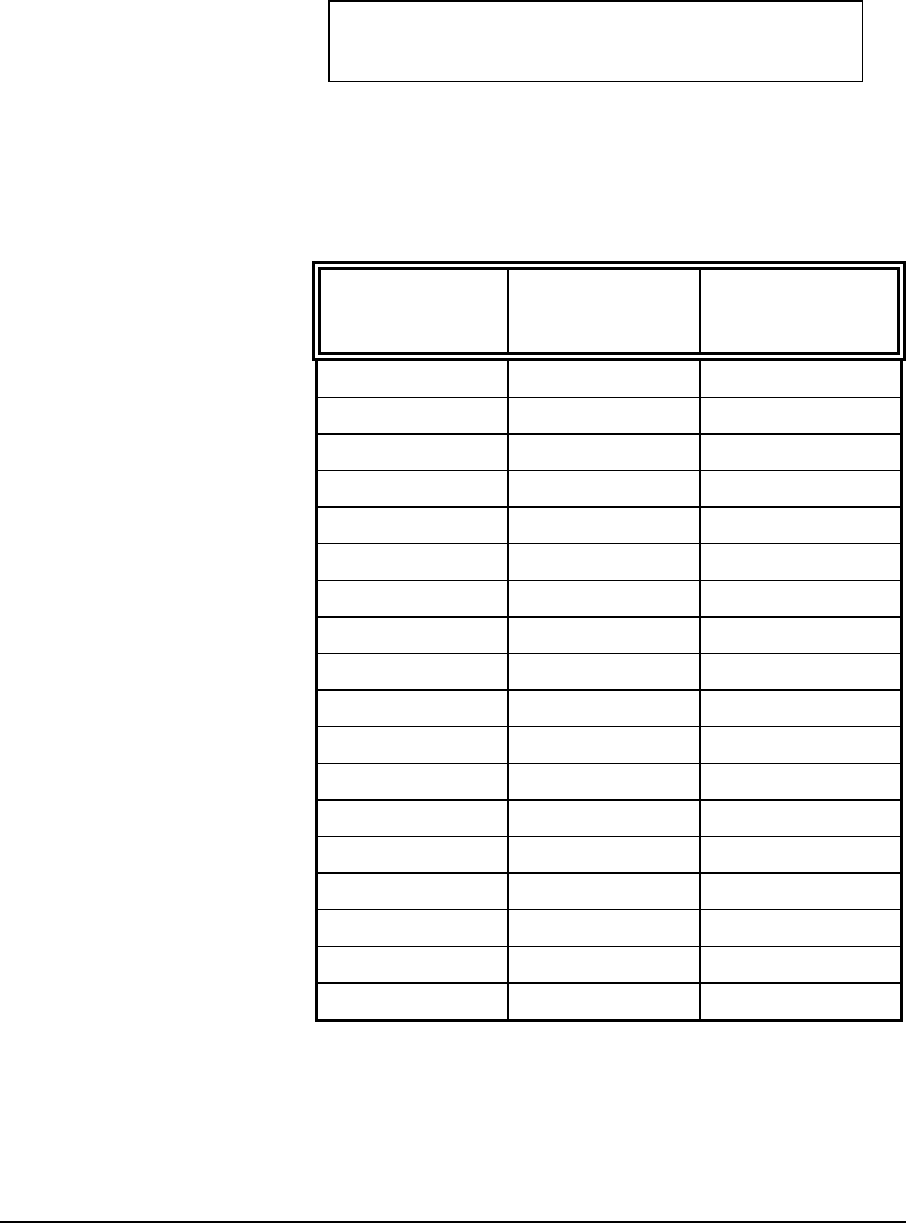
The following tables list the PCI Active Analysis Probe cable
headers and the corresponding PCI Local Bus signals after
these signals have been terminated by the 90K ohm/10pf
terminators.
Analysis Probe
Cable Header and
Pin number
Logic Analyzer
channel number
PCI Signal name
Header 1 pin 3 CLK/16 PCI Clock
5 no connect
7 15 FRAME#
9 14 IRDY#
11 13 TRDY#
13 12 STOP#
15 11 DEVSEL#
17 10 L_CMD3
19 9 L_CMD2
21 8 L_CMD1
23 7 L_CMD0
25 6 C/BE3#
27 5 C/BE2#
29 4 C/BE1#
31 3 C/BE0#
33 2 RST#
35 1 PERR#
37 0 INTx#
38