


Alcatel OmniAccess 6000 LC-2G24FP Installation Instructions 5
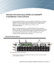
The first line card should be installed in Slot 2 of the Alcatel Wireless LAN
Switch chassis. A second optional line card can be installed in Slot 3, and a
third in Slot 1. A line card cannot be installed in Slot 0.
If you are replacing a previously installed module, first see “Removing a Line
Card”.
To install a module in a previously empty bay, remove the blank cover plate
first. To do this, use a #2 Phillips or cross-head screwdriver to loosen both of
the fastening screws on the blank cover place. The screws loosen with
counter-clockwise rotation, but are captive and cannot be fully removed.
Carefully insert the line card into the chassis slot.
Engage the line card.
There may be moderate resistance when the line card meets the connectors in
the backplane. Press firmly so that the connectors at the back of the module
engage with the backplane, but do not use excessive force.
If the system is powered up, the module’s Power LED will light up green if the
line card is inserted properly.
Secure the line card.
Use a #2 Phillips or cross-head screwdriver to push in the captive fastening
screws and turn them clockwise until moderate resistance is felt. Do not
over-tighten.
Connect the appropriate network cables.
Removing a Line Card
The line card is hot-swappable and can be removed from the Alcatel Wireless
LAN Switch chassis while system power is on or off.
Make sure you understand the procedure and all precautions.
CAUTION—If installing a line card in Slot 1, make sure that the fastening
screws for the module in the slot above it are fully secured. If the
module in Slot 3 is loose, it could interfere with the new module
insertion and possibly damage the components.
3
4
5
6
CAUTION—This procedure should be performed only by a trained
technician.
1