


Software Release 2.3.1 19
Software Release 2.3.1
C613-10325-00 REV B
redirection any web traffic from the user’s PC or laptop can be redirected to the
ISP's web server. This forces the user to arrange payment for using the service
before being able to browse to any other site. With appropriate supporting
“deny” rules, all other traffic types from the user’s PC can be blocked until
payment has been made.
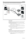
The following gives a simple example of how a system such as this would be
configured. The ISP has a switch configured with a firewall. The switch’s
VLANs, vlan1 and vlan2, are private and public interfaces respectively. The
ISP’s web server has the IP address 205.1.28.6. The following rules perform the
web redirection and the blocking of all non-web traffic:
ADD FIREWALL POLICY=ISP RULE=298 INTERFACE=vlan1 ACTION=NAT
NATTYPE=REVERSE PROTOCOL=TCP PORT=80 GBLREMOTE=205.1.28.6
ADD FIREWALL POLICY=ISP RULE=299 INTERFACE=vlan1 ACTION=DENY
PROTOCOL=ALL
Once a user has arranged payment, a rule can be added that specifies the IP
address that the ISP has assigned to the user, allowing the user full access to the
service. The following is an example of such a rule. The user has been allocated
the IP address 10.8.0.172. It is important that the rule number is lower than the
blocking and redirecting rules, because rules are tried in order from the lowest
rule number until a match is found. A low number will ensure that the allow
rule will be applied if appropriate, rather than any of the other rules.
ADD FIREWALL POLICY=ISP RULE=5 INTERFACE=vlan1 ACTION=ALLOW
IP=10.8.0.172 PROTOCOL=ALL
If the ISP wishes to take advantage of the time limited rules feature, allowing
the user to have access for 30 minutes, the following rule would be used
instead.
ADD FIREWALL POLICY=ISP RULE=5 INTERFACE=vlan1 ACTION=ALLOW
IP=10.8.0.172 PROTOCOL=ALL TTL=0:30
Further Examples
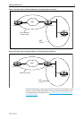
Firewall and IPsec Tunnel
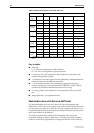
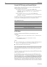
Enhanced NAT can facilitate routing across an IPsec tunnel, when one end of
the tunnel has separate IPsec and default gateways (Figure 5 on page 20). In the
following example, the router at the LAN 1 end of the tunnel has an IP address
of 192.168.2.100, and the LAN 2 end of the tunnel has an IP address range of
192.168.1.1-192.168.1.100. The IP address of traffic originated by LAN 1 hosts is
translated to 192.168.1.53, using the command (applied to the private eth0
interface of the LAN 1 gateway router):
ADD FIREWALL POLICY=zone1 RULE=7 ACTION=NAT NATTYPE=ENHANCED
INT=eth0 PROTOCOL=all IP=192.168.2.0-192.168.2.255
REMOTEIP=192.168.1.1-192.168.1.100 GBLIP=192.168.1.53
The traffic will appear to devices on LAN 2 to originate locally. When a PC in
the subnet 192.168.1.1-192.168.1.100 tries to reply to a packet from a host in
LAN 1 (subnet 192.168.2.0), the IPsec gateway will reply to the PC’s ARP
request with proxy ARP. The packet will be successfully routed through the
tunnel instead of through the default gateway.