


10 AT-8600 Series Switch
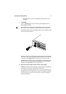
9. Apply AC power to the switch
Plug the power cord into the AC power connector. This is on the switch’s
rear panel, as shown in the below figures.
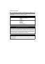
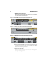
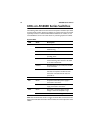
Figure 1: AT-8624T/2M front and rear panel with AC power inlet.
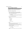
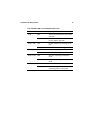
Figure 2: AT-8624PoE front and rear panel with AC power inlet
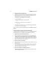
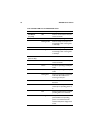
Figure 3: AT-8648T/2SP front and rear panel with AC power inlet
10. Check that the PWR LED on the switch’s front panel lights green
If the PWR (power) LED fails to light, refer to the AT-8600 Series Hardware
Reference for troubleshooting information.
11. Connect the data cables
Make sure each cable connection is secure. The switch will now perform
basic Layer 2 switching functions.
1 3 5 7 9 11 13 15 17 19 21 23
24681012141618202224
LINK
MODE
LINK
MODE
FAULT
RPS
MASTER
PWR
1357911
2 4 6 8 10 12
13 15 17 19 21 23
14 16 18 20 22 24
26
COL
100
FULL
ACT
AT-8624T/2M
Layer 3 Fast Ethernet Switch
MODE
RS-232
TERMINAL PORT
STATUS
25
1357911131517192123
2 4 6 8 10 12 14 16 18 20 22 24
FAULT
RPS
MASTER
PWR
MODE
1357911
2 4 6 8 10 12
13 15 17 19 21 23
14 16 18 20 22 24
STAT US
26
RS-232
TERMINAL PORT
COL
HALF DUP
FULL DUP
ACT100 LINK 10 LINK ACT
PD ON MAX CURRENTPD ERR
AT-8624POE
Layer 3 Fast Ethernet Switch
25
SFP
50
STATUS
49
LINK 49R MODE
LINK 50R MODE
LINK
LINK
MODE
COL
SPD
FDX
ACT
FLT
MSTR
RPS
PWR
CLASS 1
LASER PRODUCT
DO NOT STARE
INTO BEAM
AT-8648T/2SP
Layer 3 Fast Ethernet Switch