


Installation & Safety Guide 9
• Mount the switch in the rack using standard screws (these are not
provided).
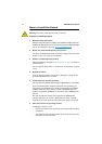
7. Install SFPs
For the AT-8648T/2SP, you may also need an optional SFP (Small Form-
factor Pluggable module).
Do not look into the optical ports of SFP cables or transceivers. Invisible
laser radiation may be emitted from disconnected fibres or connectors.
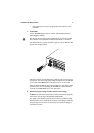
The SFP transceivers must be inserted the right way into the SFP 49 or SPF
50 slots. See the figure below.
Slide the transceiver into the SFP socket, and firmly press it until it engages.
To remove it, first release it by gently pulling the release lever, and then pull
it out of the socket. Never force a transceiver into or out of a socket.
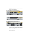
When an SFP is installed into one of the two SFP ports, that SFP port takes
precedence over its corresponding 10/100/1000T port. When the SFP is
removed, the 10/100/1000T port is once again active.
8. Check the supply voltage and the switch’s rated voltage
AT-8600 Series switches are fitted with a universal main power supply that
will function over the range 100–240 VAC and 50–60 Hz.
The specific power supply requirements for a particular model are clearly
displayed on the rear or underside of the switch. If the supply is outside the
accepted range for the switch, the switch may not operate or damage to
the switch may result.