


8 AT-8600 Series Switch
How to Install the Switch
Warning All versions of this equipment must be earthed.
Prepare to install the switch
1. Read the safety information
Read the safety information included in this Installation & Safety Guide. This
Installation & Safety Guide is also on the Documentation and Tools CD-ROM
and you can download a copy from http:// www.alliedtelesis.com
.
2. Gather the tools and equipment you will need
You will need a Phillips #2 flat-head screwdriver and cage nuts to attach the
brackets to your rack. These are not supplied.
3. Choose a suitable operating location
Follow the guidelines described in “Selecting a Site” on page 7 to choose a
suitable location.
You can install the switch either in a 19-inch rack, on a flat bench, or against
a wall.
4. Unpack the switch
Verify the package contents. If any items are damaged or missing, contact
your authorised distributor or reseller.
5. Install expansion modules (optional)
The only expansion module supported by the AT-8624T/2M is the AT-A46.
If you purchased expansion modules, install them now by following the
instructions in the AT-A 45 /xx Ser ies , AT-A 46 , an d AT-A 47 Exp an si on Mod ule s
Installation Guide that comes with the modules. The AT-A46 expansion
module is supported by AT-8000 Series switches as well as AT-8600 Series
switches.
Hot swap of expansion modules is not supported on AT-8624T/2M
switches. If you insert or remove a module when the switch is already
powered on, you must restart the switch before the module can be used.
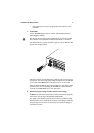
6. Place the switch in its operating location
If installing the switch in a rack:
• Remove the rubber feet on the bottom of the switch with a flat-head
screwdriver.
• Attach the two rack-mounting brackets to the switch with the screws
provided in the rack-mount kit.