


AT-2911 Series Gigabit Ethernet Network Adapters Installation and User’s Guide
39
Connecting the Network Cables
After you install an AT-2911 series adapter in your desktop computer,
attach the system to a compatible link partner or an IEEE 802.3 compliant
Gigabit Ethernet switch. The adapter has a fiber optic connector, copper
connector, SFP slot, or a combination of these connectors.
Note
You must have a fiber optic or copper cable to connect your system
to the network. If your adapter has an SFP slot, you must have an
SFP transceiver as well. Contact your Allied Telesis distributor of
reseller for a list of supported transceivers.
Fiber Optic Cable The AT-2911 series fiber optic adapters are equipped with two types of
fiber optic connectors: SC and LC connectors. For optical characteristics
of the AT-2911 adapter, see Appendix A, “Specifications” on page 111. In
addition, the AT-2911 data sheet is available on the Allied Telesis website:
www.alliedtelesis.com.
To connect a fiber optic network cable to the adapter, perform the
following procedure:
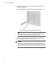
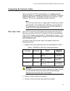
1. Prepare a fiber optic cable according to the specifications in Table 3.
Warning
The fiber optic ports contain a Class 1 laser device. When the ports
are disconnected, always cover them with the provided plug.
Exposed ports may cause skin or eye damage.
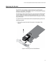
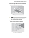
2. Remove a rubber plug from the adapter.
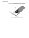
3. Connect one end of the fiber optic cable to the adapter.
Table 3. 1000BASE-X Fiber Optic Cable Specifications
Port Type Connector Media
Maximum
Distance
1000BASE-SX Fiber Optic 50 µm multimode
850 nm
550 meters
(1,804 feet)
1000BASE-SX Fiber Optic 62.5 µm multimode
850 nm
275 meters
(853 feet)
1000BASE-LX Fiber Optic 9.125 µm single mode
1310 nm
10 kilometer
(6.213 miles)