


Chapter 1: Overview
18
AT-9424T/GB
Switch
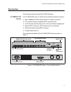
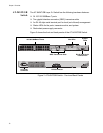
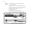
The AT-9424T/GB Layer 2+ Switch has the following hardware features:
24 10/100/1000Base-T ports
Two gigabit interface connector (GBIC) transceiver slots
An RJ-45 style serial terminal port for local (out-of-band) management
Status LEDs for the ports, transceiver slots, and system
Redundant power supply connector
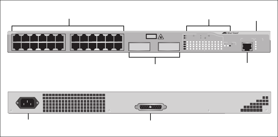
Figure 2 shows the front and back panels of the AT-9424T/GB Switch.
Figure 2 AT-9424T/GB Switch - Front and Back Panels
AC Power
Connector
RPS Connector
10/100/1000Base-T Ports
GBIC Transceiver Slots
Port and Transceiver
FAULT
RPS
MASTER
POWER
GBIC
23
GBIC
24
CLASS 1
LASER PRODUCT
STATUS
TERMINAL
PORT
1357911
2468 10 12
13 15 17 19 21 23R
14 16 18 20 22 24R
AT-9424T/GB
G
i
gab
i
t
E
t
h
er
n
et
S
w
i
tc
h
1 3 5 7 9 11 13 15 17 19 21 23R
2468 10 12 14 16 18 20 22 24R
23 24
L/A
D/C
D/C
L/A
D/C
L/A
1000 LINK / ACT
HDX /
COL
FDX
10/100 LINK / ACT
PORT ACTIVITY
L/A
1000 LINK / ACT
GBIC
RJ-45 Style Serial
Terminal Port
System
LEDs
Slot LEDs
RPS INPUT
100-240VAC~