


Chapter 1: Overview
38
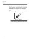
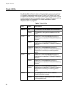
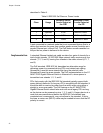
Stack LEDs
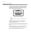
The Stack LEDs reflect the status of the two Stack ports on the optional
AT-StackXG Stacking Module for the AT-9424Ts, AT-9424Ts/XP, and
AT-9448Ts/XP Switches. The module, which does not have LEDs, is used
to build a stack of up to five or eight devices. These LEDs remain off if the
optional module is not installed. For further information, refer to
“Expansion Slot” on page 39.
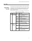
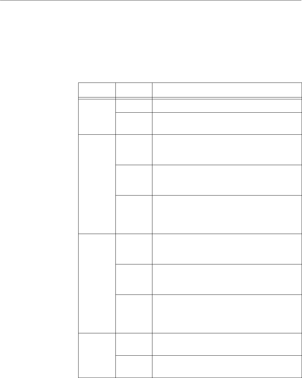
Table 7 Stack LEDs
LED State Description
MSTR Off The switch is not the master unit of the stack.
Green The switch is acting as the master unit of the
stack.
1 L/A Off Stack Port 1 has not established a link to a
stacking port on another AT-StackXG Stacking
Module.
Green Stack Port 1 has established a link to a
stacking port on another AT-StackXG Stacking
Module.
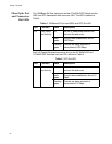
Flashing
Green
Stack Port 1 has established a link to a
stacking port on another AT-StackXG Stacking
Module and is sending or receiving packet
traffic.
2 L/A Off Stack Port 2 has not established a link to a
stacking port on another AT-StackXG Stacking
Module.
Green Stack Port 2 has established a link to a
stacking port on another AT-StackXG Stacking
Module.
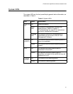
Flashing
Green
Stack Port 2 has established a link to a
stacking port on another AT-StackXG Stacking
Module and is sending or receiving packet
traffic.
PRES Off The expansion slot for the AT-StackXG
Stacking Module is empty.
Green The AT-StackXG Stacking Module is installed
in the expansion slot.