


Chapter 1: Overview
26
LEDs
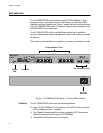
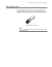
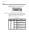
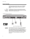
The following sections describe the PoE, twisted pair port, SFP, and
system LEDs. See Figure 3 for an illustration of the LEDs on an AT-
GS950/8 POE switch.
Figure 3. Port LEDs on an AT-GS950/8POE Switch
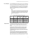
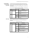
PoE LEDs The AT-GS950/8POE switch has four PoE ports and four corresponding
PoE LEDs. The PoE LEDs signal a connection to a powered device and if
the port exceeds its power budget. The PoE LEDs apply to ports 1 through
4. For more information about PoE, see “Power over Ethernet” on
page 22.
Table 3 describes the LEDs for the PoE ports.
GS950/8POE
8 Port 10/100/1000Mbps + 2 SFP Combo WebSmart Switch
1234567R 788R
POWERRESET
1
PORT ACTIVITY
ACT
1000 LINK
100 LINK
ACT
ACT
SFP
1347
Table 3. PoE LEDs
LED Function State Description
PoE Power
over
Ethernet
Off The port is not connected to a valid
powered device and power is not
being supplied to the port.
Green The port detects a valid powered
device and power is being supplied
to the port.
Amber The power required by the
connected device exceeds the port’s
power budget.
Flashing
amber
The power budget for the switch was
exceeded when the powered device
was connected to this port.