


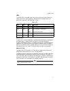

6
4. Verify that the PWR LED lights green.
5. Set the unit in Link Test mode
6. Remove the dust cap from the fiber optic connectors.
7. Plug the appropriate fiber cable into the connector. See Table 3 for IEEE
802.3u cabling specifications
8. Connect the other end of the fiber cable to the desired end station. Verify
that the link LED is ON.
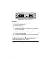
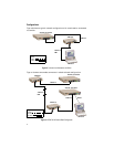
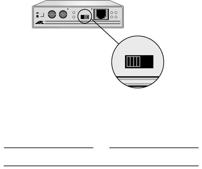
9. If you are making a direct connection to a workstation using straight-
through cable, set the MDI/MDI-X switch to the MDI-X position. (MDI-X is
the default position.)
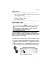
If you are connecting the media converter to a hub, switch, or another
media converter with a straight-through cable, set the MDI/MDI-X switch
to the MDI position. See Figure 7.
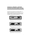
Figure 7
MDI/MDI-X Switch
10. Plug a Category 5 twisted pair cable into the RJ45 connector. Connect the
other end of the twisted pair cable to the desired end station. Verify that
the Link LED is ON
11. Set the unit to Normal (NML) Mode for normal operation.
Note
End stations used with the media converter must operate in the same
duplex mode (either both full-duplex or both half-duplex).
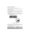
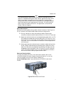
100Base-FX
REC
LNK
100Base-TX
REC
LNK
PWR
NML
TX RX
MC101XL FAST ETHERNET MEDIA CONVERTER
MDI MDI-X
NML
LNK TST
C
K
MDI MDI-X