


Installation Guide
3
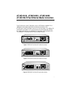
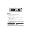
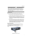
LEDs
The PWR LED in the upper right corner of the front panel lights when the
media converter is receiving power. Status LEDs are located on the front
panel next to each port and described in Table 1.
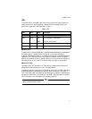
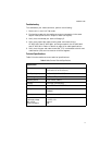
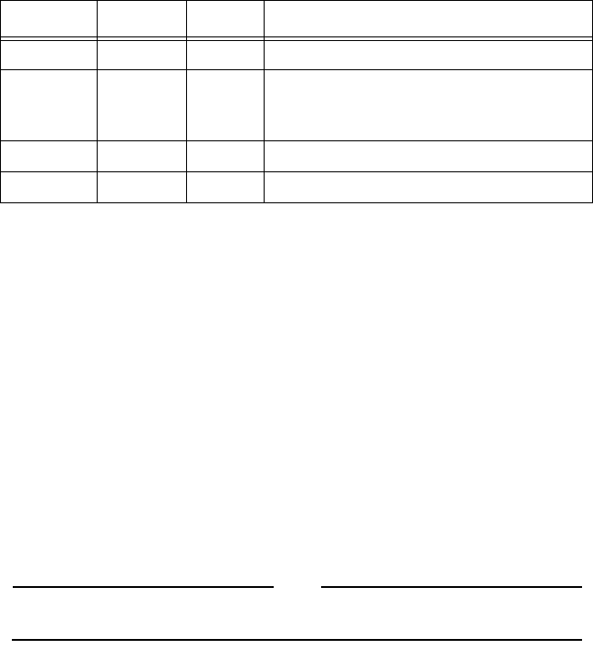
Table 1
LEDs
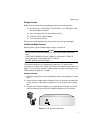
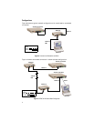
MDI/MDI-X Switch
The MDI/MDI-X (Media Dependent Interface/Media Dependent Interface with
Crossover) switch, located on the front panel, is a straight-through or
crossover cable selection switch. It enables the RJ45 port to be connected to a
repeater or DTE device without using a special crossover cable. The default
position of the switch is MDI-X, which means you can connect the RJ45 port to
a workstation or to any other DTE device using a straight-through cable.
NML/LNK TST Switch
The NML/LNK TST (Normal/Link Test) switch, located on the front panel,
establishes a fiber/twisted pair link in the test position.
The default position of the switch is IN, which is the normal (NML) operating
mode and enables the MissingLink feature. With the switch in the OUT or
Link Test mode (LNK TST) position, the MissingLink feature is disabled and
the optical transmitter TX is forced on. The NML LED lights when the NML/
TST LNK switch is in the default (IN) operating position.
Note
Using the Link Test mode does not interfere with the media converter’s
ability to pass network traffic.
LED Color State Description
PWR Green
ON
Power is applied.
NML Green
ON
OFF
Unit is operating in normal mode.
Unit is in Link Test mode.
REC Green
ON
Data is being received on the port.
LNK Green
ON
Link established on the port.