


6 AT-PWR01 & AT-PWR01-80
C613-04049-01 REV B
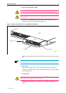
8. Apply power to the PSU
For AC Models:
Read the AT-PWR01 Safety and Statutory Information booklet before
connecting a PSU to an external AC power source. A copy of the safety
booklet is included with each PSU.
Plug the provided AC power cord into the AC power inlet on the rear
panel of the PSU and connect the PSU to the mains power supply.
Important information for service personnel only:
• CAUTION: double pole/neutral fusing
• The ratings of fuses FH101 and FH102 is 250 V, 5 A
For DC models:
Read the AT-PWR01 Safety and Statutory Information booklet before
connecting a PSU to a DC power source. A copy of the safety booklet is
included with each PSU.
Only trained and qualified personnel should connect a DC power supply.
For centralized DC power connection, the switch should be installed only in
Restricted Access Areas (Dedicated Equipment Rooms, Equipment Closets, or
the like) in accordance with Articles 110-16, 110-17, and 110-18 of the National
Electrical Code, ANSI/NAPA 70.
DC supply cable specifications:
• Three core cable is required
• Minimum core size: 3.3 mm
2
(12 AWG) high strand count copper wire
• Minimum cable rating: 600 V, 90 degrees Celsius
DC power supply specifications:
• 40 to 60 V, 48 V nominal
• Supports either positive grounded or negative grounded operation
Circuit protection:
• 10 Amp certified/Listed circuit breaker is required for branch circuit
protection
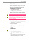
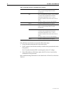
To connect the DC supply:
Ensure that the supply cable is not live.
1. Remove the transparent protective terminal cover.
2. Strip the supply cable wires to expose 7.5mm (0.31 in.) of bare
conductor. Terminate with JST FN5.5-5 or equivalent, using a crimp
tool.
3. Connect the ground wire to the ground terminal. Terminals can be
identified by the diagram on the switch’s rear panel. Tighten the
terminal to between 2.4 and 4.0 Nm (21.3 and 35.4 lbf in).