


8 AT-PWR01 & AT-PWR01-80
C613-04049-01 REV B
If the PSU does not function as expected, follow these steps:
1. Check all cable connections are correct and secure.
2. For DC models, check that the standby switch has been pressed and is in the
ON position.
For AC models, check the PSU is receiving the correct AC voltage.
3. If the LEDs indicate a PSU fault, replace the PSU or have it serviced by
authorised service personnel.
More troubleshooting information can be found in the AT-8900 Series Hardware
Reference.
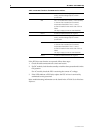
Table 3: PSU LEDs found on all AT-8900 Series switches
PSU 1 Green PSU 1 is installed and supplying power to the
switch, and the voltage output is within
specification.
Red PSU 1 is installed in the switch, a fan has failed,
or the PSU has exceeded its recommend
temperature threshold of 75º C (167º F).
A FOM is installed in the switch and a fan has
failed.
The bay is empty (no PSU or FOM installed).
Not lit A FOM is installed and the fan is good.
PSU 2 Green PSU 2 is installed and supplying power to the
switch, and the voltage output is within
specification.
Red PSU 2 is installed in the switch, a fan has failed,
or the PSU has exceeded its recommend
temperature threshold of 75º C (167º F).
A FOM is installed in the switch and a fan has
failed.
The bay is empty (no PSU or FOM installed).
Not lit A FOM is installed and the fan is good.