


Quick Install Guide 7
C613-04049-01 REV B
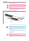
4. Connect the positive feed to the + (positive) terminal and the negative
feed to the - (negative) terminal. Tighten the terminals to between 2.4
and 4.0 Nm (21.3 and 35.4 lbf in).
Check that the PSU terminals are wired to the correct polarity. A PSU will be
damaged if incorrectly connected.
5. Ensure there are no exposed cable strands.
6. Replace the transparent plastic terminal cover.
The transparent plastic terminal cover must be replaced.
7. Secure the supply cable (to the rack framework or similar object) so that
the connections are isolated from any force applied to the cable.
8. Ensure the circuit breaker (for the supply circuit) and the Run/Standby
switch (on the switch) are in the OFF position.
9. Connect the supply cable wires to the circuit breaker.
10. Switch the power switch to the ON position.
9. Check the PSU LEDs
Each PSU has LEDs that indicate the PSU’s operational status.
Once you have inserted the PSUs and powered on the chassis, check the
LEDs for correct operation using the table below as a guide (see Table 2).
On the front panel of the switch there are two LEDs that indicate the
operational status of each PSU installed in the switch (see Table 3).
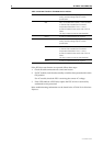
Table 2: LEDs on AC and DC PSUs
LED State Function
Fault Red There is either a fan failure, or the temperature has
exceeded the specified limit of 75º C (167
º F).
PWR Green A PSU is installed and supplying power to the switch.