


Chapter 1: Overview
30
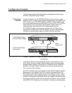
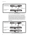
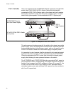
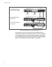
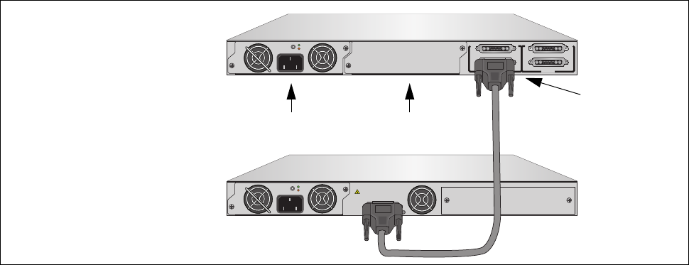
PoE+ Switches Here is an example of the AT-RPS3000 Chassis supporting a single PoE+
switch, the AT-x610-24Ts/X-POE+ Switch. Notice that the switch is
connected to RPS 2 PoE+/System port on the chassis so that it receives
both system and PoE+ power from the power module in slot A. It would
receive only system power if it was connected to RPS 1 System port.
Figure 14. Example of One PoE+ Switch
The active source of system power for the switch is its internal, removable
power supply. This is in keeping with the rule that PoE+ switches gain their
system power from their internal power supply, and use the power supply
in the AT-RPS3000 Chassis as a redundant supply for system power.
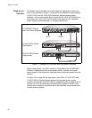
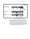
It is important to note, however, that the principal of active and redundant
system power does not apply to PoE+ power because the AT-RPS3000
Chassis supplements the PoE+ power from the switch’s internal power
supply, thus allowing for more powered devices on the switch.
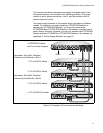
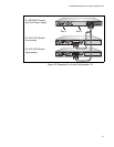
The AT-PWR800 and AT-PWR1200 Modules can provide PoE+ power to
just one switch at a time. Consequently, the chassis must have a second
module if it is to support two PoE+ switches. In Figure 15 on page 31, the
AT-x610-24Ts/X-POE+ and AT-x610-48Ts/X-POE+ Switches receive
redundant system power and additional PoE+ power from the modules in
slot A and B, respectively.
B
B
1
2
3
4
SYSTEM
PoE+ / SYSTEM PoE+ / SYSTEM
SYSTEM
MODULE B
MODULE A
A
A
AT-PWR800
DC OUT
FAULT
100-240 VAC~12A MAX
AT-PNL800/1200
POWER SUPPLY
RPS
READY
RPS INPUT
12V/21A MAX
WARNING
This unit may have more than one power input. To reduce the risk of
electric shock, disconnect both A/C and RPS inputs before servicing
unit.
AT-PWR800
2142
DC OUT
FAULT
100-240 VAC~12A MAX
AT-x610-24Ts/X-POE+ Switch
AT-RPS3000 Chassis
(Low-power)
with One Power Supply
RPS 2
PoE+/System
Port
Slot A
Slot B