


Chapter 3: Removing Power Supply Modules
76
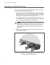
Removing the AT-RPS-CBL1.0 Cable
Here are the steps to removing the AT-RPS-CBL1.0 cable from an RPS
port on the AT-RPS3000 Chassis and switch:
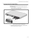
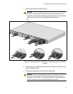
1. On the front panel of the AT-RPS3000 Chassis, examine the CABLE
LED of the RPS port to which the AT-RPS-CBL1.0 cable is connected.
If the LED is off, go to the next step. If the LED is green, press the On/
Off button to turn off the port. The LED should turn off.
For example, if you want to disconnect the cable from RPS port 3 on
the AT-RPS3000 Chassis, check the CABLE LED for port 3. If the LED
is on, press the port’s On/Off button to disable the port.
Caution
Never connect or disconnect an RPS cable from an RPS port on an
operational AT-RPS3000 Chassis without first turning off the port.
Failure to disable an RPS port may damage the redundant power
supply system.
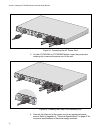
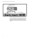
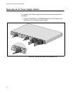
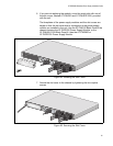
2. Loosen the two thumbscrews that secure the cable to the RPS port on
the AT-RPS3000 Chassis.
Figure 56. Loosening the Thumbscrews that Secure the AT-RPS-CBL1.0
Cable to the AT-RPS3000 Chassis
B
B
1
2
SYSTEM
PoE+ /
SY
STEM
PoE+ /
SY
STEM
SYSTEM
MODULE B
MODULE A
AT-PWR800
DC OUT
FAULT
2211
1
0
0
-2
4
0
V
A
C
~
1
2
A
M
A
X