


Chapter 1: Overview
48
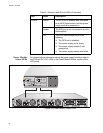
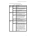
Guidelines
Here is a summary of the rules and guidelines discussed in this chapter:
Caution
The AT-RPS3000 Chassis is designed specifically for the x610
Series of Layer 3 Gigabit Ethernet switches. It should not be used
with any other product.
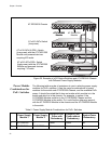
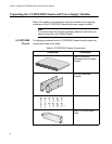
You may install up to two power supply modules in the chassis.
The power supply module in slot A (left-hand slot as you face the rear
panel) provides power to the RPS 1 System and RPS 2 PoE+/System
ports.
The power supply module in slot B (right-hand slot) provides power to
the RPS 3 System and RPS 4 PoE+/System ports.
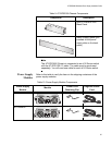
The AT-RPS3000 Chassis can support two power modules of the
same type, such as two AT-PWR800 Modules, or one AT-PWR800
Module and one AT-PWR1200 Module. All other combinations are not
allowed, as explained in “Power Supply Modules” on page 19.
The AT-PWR250 Power Supply Module may be used to provide
system power to two low-power switches or one high-power switch.
The module does not provide PoE+ power,
The AT-PWR800 and AT-PWR1200 Modules may be used to supply
system power to two low-power switches or one high-power switch.
They may also be used to provide 480W or 780W, respectively, of
additional PoE+ power to one PoE+ switch.
You may use the AT-PWR800 and AT-PWR1200 Modules in the
AT-RPS3000 Chassis to provide redundant system power to non-
PoE+ switches. The modules provide redundant system power but no
power for PoE+ for non-PoE+ switches.
You may connect a non-PoE+ switch to either an RPS System or RPS
PoE+/System port on the chassis.
The AT-PWR800 and AT-PWR1200 Modules can supply PoE+ power
to just one switch at a time.
A PoE+ switch has to be connected to the RPS 2 or 4 PoE+/System
port to receive PoE+ power from the chassis.
The power supply in the switch does not have to be the same type as
the power supply in the AT-RPS3000 Chassis. For example, a switch
that contains the AT-PWR250 Module may be connected to an
AT-PWR1200 Module in the AT-RPS3000 Chassis.
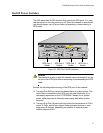
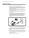
If the chassis is operational, you should always turn off an RPS port
with the appropriate On/Off port switch, in the LED panel, before
connecting or disconnecting an RPS cable.