


AT-RPS3000 Redundant Power Supply Installation Guide
63
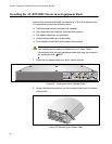
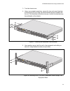
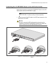
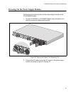
3. Secure the module to the chassis by tightening the two captive screws.
Figure 41. Securing a Power Supply Module
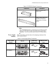
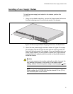
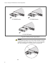
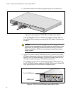
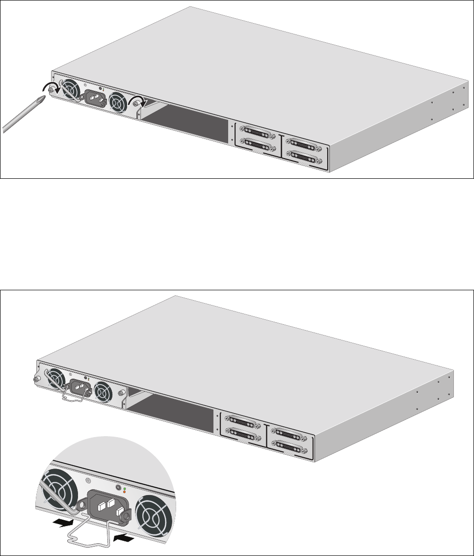
4. For the AT-PWR250 or AT-PWR800 Module, install the power cord
retaining clip on the AC power socket by pressing the sides of the clip
inward and inserting the two ends into the holes on the power socket.
(The AT-PWR1200 Module does not come with a power cord retaining
clip.)
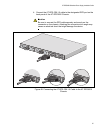
Figure 42. Installing a Power Cord Retaining Clip
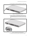
5. To install a second power supply module, repeat steps 2 through 4.
B
B
1
2
3
4
SYSTEM
PoE+ /
SYSTEM
PoE+ /
SYSTEM
SYSTEM
MODULE B
MODULE A
A
A
AT- P WR 800
D
C
O
U
T
F
A
U
L
T
2176
100-240
VAC
~12A
MAX
B
B
1
2
3
4
S
Y
S
T
E
M
P
o
E
+
/
S
YS
T
E
M
P
o
E
+
/
S
Y
S
T
E
M
S
Y
S
T
E
M
MODULE B
MODULE A
A
A
AT-PWR800
D
C
O
U
T
F
A
U
L
T
DC O
UT
FAU
LT
2153
1
0
0
-
2
4
0
V
A
C
~
1
2
A
M
A
X
100-240 VAC
~12
A MAX