


Chapter 2: Installation
52
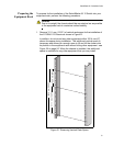
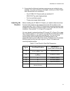
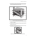
2. Identify the lowest 1/2” screw hole pattern on the rack mounting rails
within the space reserved for the AT-SBx3112 Chassis. Install one
rack mount screw in each vertical rail - at the same height in the top
screw hole of the lowest 1/2” hole pattern as displayed in Figure 22.
The screws are used to support the chassis while you secure it to the
rack.
Figure 22. Rack Mounting Hole Locations
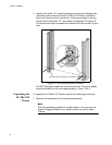
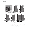
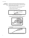
Do NOT fully tighten these two screws at this time. The screw heads
should protrude from the rack approximately 6.4 mm (.25 in).
Unpacking the
AT-SBx3112
Chassis
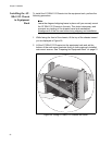
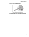
To unpack the AT-SBx3112 Chassis, perform the following procedure:
1. Remove all components from the shipping package.
Note
Store the packaging material in a safe location. You must use the
original shipping material if you need to return the unit to Allied
Telesis.
1791
Top screw hole of the lowest 1/2” hole pattern
6.4 mm (.25 in) away from rack
Screw
Head