


SwitchBlade x3112 Installation Guide
61
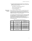
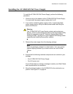
Installing the AT-SBx3161 System Power Supply
The SwitchBlade x3112 can host up to four power supplies consisting of
two AT-SBx3161 System Power Supplies and two AT-SBx3165 PoE
Power Supplies. The AT-SBx3112 Chassis comes with three blank power
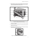
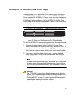
supply panels in chassis slots A, B, and C as displayed in
Figure 33. Slot
D is left open for the installation of the first AT-SBx3161 System Power
Supply. Keep the blank power supply panels in place on the unused slots
to insure proper chassis airflow.
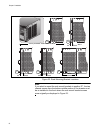
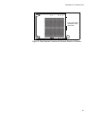
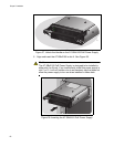
Figure 33. Slots A to D for System and PoE Power Supplies
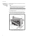
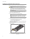
To install the AT-SBx3161 power supply, perform the following procedure:
1. Choose a slot in the chassis for the AT-SBx3161 System Power
Supply. You can install the system power supply in either slot C or D. If
this is the initial installation of the chassis, Allied Telesis recommends
slot D because it does not have a blank power supply panel installed.
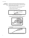
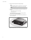
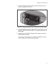
2. If you want to install the power supply in slot C, remove the blank
power supply panel by lifting the blank panel handle and lifting the
panel out of the slot.
Note
If you are installing one power supply and choose slot C, then install
the blank power supply panel that came from slot C and install it in
slot D to insure proper chassis airflow. Close the handle to secure it
in to the chassis.
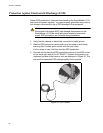
Warning
The AT-SBx3161 System Power Supply contains active electronic
devices, which can be damaged by electro-static discharges (ESD).
Follow the procedure given in “Protection Against Electrostatic
Discharge (ESD)” on page 60 to guard against ESD damage when
unpacking and installing these power supplies.
CD
AT-SBx3161 System Power Supply Slots
AB
AT-SBx3165 PoE Power Supply Slots
1891
P
O
E
S
Y
S
T
E
M
P
O
E
S
Y
S
T
E
M
SB 31FAN