


SWITCHERS
7
7
STEP
:
This feature allows cycling through the inputs
one at a time. It is used to select the next input
from an ALL OFF condition. If this button is
pressed once it switches to the next input in an
increasing order. For example, if INPUT 3 is
currently selected, pressing STEP SELECT
once will switch to INPUT 4. If pressed again
INPUT 5 is selected. If INPUT 6 is already
selected, and the STEP SELECT button is
pressed once, none of the inputs will be
selected. This condition is similar to the ALL
ON function. By pressing once more from the
ALL OFF stage, INPUT 1 will be selected.
7.1.3 OUTPUT CONTROL SECTION
DELAY
:
This function enables Sync Delay Switching in
RGBHV and RGBS signals. Sync Delay allows
the ”glitch” that normally takes place when
switching between high-resolution sources to
take place off screen. When the Sync Delay
feature is enabled, the video portion of the
image (RGB signals) is disconnected before
the sync portion (H&V SYNC or CSYNC).
When connecting the input, the video portion
of the signal (RGB) is restored shortly after the
incoming sync portion of the signal is
connected. This delay time is factory pre-set to
2.5 seconds. By pressing this button once, the
SYNC DELAY feature is enabled and
confirmed through the LED on top of the
button. If it is pressed once more this feature
is disabled and the LED turns off.
VIDEO
OFF
:
This feature allows a user to disable only the
video (RGB channels) portion of the selected
source. The sync portion (H&V, SYNC or
CSYNC) of the selected source will continue to
be sent to the display. This feature can be very
helpful when the user does not want the
display to go into a ”no display”
or “no signal”
mode (e.g. some data monitors will display a
blue screen if no signal is present). To disable
the video portion of the selected input, press
the video off button once, the LED on the top
button should light up. To enable the video
portion, press the button again and the LED
will be in an OFF position. This feature is
designed to work only with RGBHV, RGBS
and RGsB format signals. It is similar to the
ALL OFF mode except that there is only sync
signal sent to the output for display.
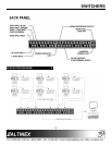
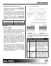
7.2 RS-232 CONTROL
The
MX2226AT
uses a terminal block type
connector for RS-232 communication. The
terminal block uses solder-free, screw-down
contacts, making it extremely easy to connect the
switcher to a control system or to a computer in
the field.
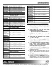
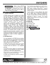
RS-232 Terminal Block
PIN DESCRIPTION
RX RS-232 receive
TX RS-232 transmit
GND Ground
LOOP Used to connect additional switchers in
”Loop” mode.
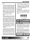
Terminal Block Designation
The terminal block is labeled with the proper
contact designations: Transmit (TX), Receive
(RX), and Ground (GND). Always remember that
the Transmit pin from the control system or
computer must be connected to the Receive pin
on the switcher control port.
Typically, a control system or computer will offer
RS-232 connections on a 9-pin D connector or a
DB 25-pin connector. The following are two typical
cable pin-out connections for RS-232 connections
from a PC. Always confirm the pin-outs for your
system to insure proper wiring.
PC DB-9 port PIN No.
MX2226AT
Terminal
block pin
3RX
2TX