


SWITCHERS
8
8
5GND
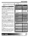
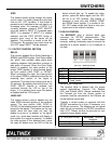
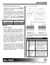
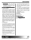
RS-232 connection of PC with DB-9 port
MX2226AT
Terminal Block
PC DB-25 port pin no.
IBM PIN No.
MX2226AT
Terminal
block pin
2RX
3TX
7GND
RS-232 connection to
MX2226AT
Terminal Block
of PC with DB-25 port
Port settings of the control system or computer
being used to control the
MX2226AT
Switcher
should be set as follows:
BAUD Rate bps (Bits per second): 2400
Data Bits: 8
Parity: None
Stop Bits: 1
There is no software or hardware flow control
implemented. The RS-232 input has a 6-character
buffer. The
MX2226AT
Switcher will not execute
additional commands until the previous command
is fully processed.
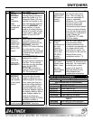
7.3 RS-232 CONTROL COMMANDS
The standard RS-232 protocol is used to control
the switcher. Commands must be issued as
shown, in ALL CAPS and with brackets [ ] that are
included in the command string.
RS-232 Protocol:
[INP0] All channels off
[INP1] Select input 1
[INP2] Select input 2
[INP3] Select input 3
[INP4] Select input 4
[INP5] Select input 5
[INP6] Select input 6
[RSET] Reset unit to user defaults
[VERN] Returns firmware version number
After processing a valid command, an [OK] string
will be returned, followed by a command echo. For
instance, if a command, [INP1] is sent to the
MX2226AT
Switcher, it would return the feedback
as [OK] [INP1]. The only exception is that with the
[VERN] command, which is the corresponding
firmware version of the switcher, [1.0] is returned
as feedback.
If a command is not recognized by the switcher,
an error string, [ERR], will be returned. Any
command other than the previously listed
commands will also return [ERR] feedback.
If the control system being used is not set up to,
pause for the [OK] string, it is important to include
a 100-millisecond delay between each command
to allow pause for the processing of the [OK]
[COMMAND] string.
The [RSET] function requires at least one minute
of processing time. If the Sync Delay function is
used, a 2.5-second delay should be maintained
between RS-232 commands, to account for the
time required processing Sync Delay switching.
If a key is pressed on the front panel, a feedback
string is transmitted. This is done to inform a
control system that the key has been pressed.
This feature allows several switchers used
simultaneously to operate in tandem.
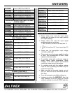
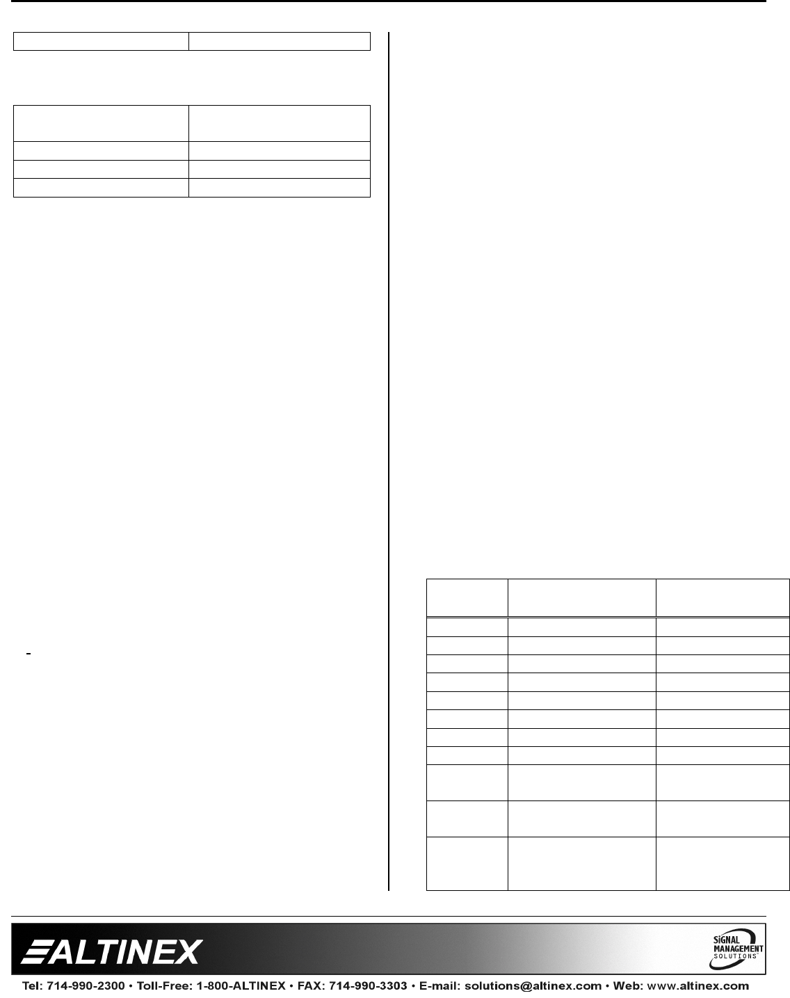
7.4 FEEDBACK CODES
Key
pressed
Description Feedback code
INPUT 1 Input Select [OK] [INP1]
INPUT 2 Input Select [INP2]
INPUT 3 Input Select [INP3]
INPUT 4 Input Select [INP4]
INPUT 5 Input Select [INP5]
INPUT 6 Input Select [INP6]
STEP Step Input select
ALL OFF Disable All Inputs [INP0]
RESET
Reset the Switcher [RSET] [INPx]
(x= default input)
VIDEO
OFF
Video RGB
(ON/OFF)
DELAY
Sync Delay
Switching
Enabled/Disabled