


SWITCHERS
9
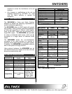
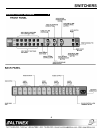
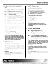
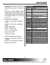
IBM PIN No.
MX2436RM
Contact
2 TX
3 RX
5 GND
Connection of IBM-PC 9-pin D to the MX2436RM
Terminal Block
Port setting preferences for the control system or
computer being used to control the switcher should
be set as follows:
BAUD RATE (Bits per second) 9600
Data bits 8
Parity None
Stop Bits 1
7.2.1 RS-232 PROTOCOL:
The RS-232 protocol for the MX2436RM
Switcher uses a simple ASCII character format.
1. Square brackets “[“ & “]” are part of the
command.
2. Use uppercase letters for all commands.
3. Make sure that the transmit pin of the
control system is connected to the
receive pin of the switcher and
connection done as per Table 4.
4. Make sure that there is a delay of 50 ms
between two consecutive commands.
The factory default settings is 2400 baud, 8 bits, 1
stop, and no parity. There is no software or
hardware flow control implemented.
The MX2436RM Switcher requires 50ms of
processing time after each command is sent. So,
please keep a 50ms delay between two consecutive
commands.
The RS-232 input has a 16-character buffer and will
not execute any command longer than 16-
characters. Any additional commands are ignored
until the previous command is fully processed. After
processing a valid command, an [OK] string will be
returned, if requested by the feedback command.
7.2.2 PROGRAMMING COMMANDS
NOTE:
These programming commands are used for
programming the switcher; they should not be
used as part of a program to operate the
switcher. The program setting changes done
through these commands are stored in a non-
volatile memory. Typically, these commands
can be issued 10,000 times before the memory
needs to be replaced.
1. [# SW n1 n2 n3 n4 n5 n6] - Video Switch Input
# = Switch number (no. from 1 to 9; default is
0).
n1 = Video input number (no. from 0 to 6)
n2 = Break Away code (0 = On; 1 = OFF)
n3 = 0, video key pressed
n4 = 0 Sync Delay. The MX2436RM
Switcher is equal to zero. It is not
necessary for the switch to delay.
n5 = Video Equalizer (Hexadecimal no. from
0 to F).
n6 = Audio Gain (Hexadecimal no. from 0 to
F).
The [# SW n1 n2 n3 n4 n5 n6] command is the
main command of the video input switcher
containing all the information needed by the
switcher to activate the video sources
connected to the unit.
Example:
Sending the [8SW61040F] command will
activate switcher module 8, Video Input number
6 and Audio Input 6 (because the breakaway
code is 1). The zero (0) will notify the switcher
that the video key was pressed with an interval
of 4 (2 seconds). The video equalizer was set to
OFF and there is a maximum volume of F. Zero
(0) = OFF and default is 8 for a normal volume
or video).