


DESIGNER SOLUTIONS
400-0503-001
13
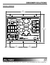
INSTALLING YOUR UT250-101 6
Step 1. Decide how the UT250-101 will be
controlled: using contact closures on the
Output Select Controls, through computer
control using the RS-232 input, using
auto-switching, or all 3 methods.
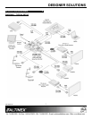
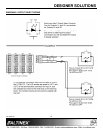
If using the Output Select Controls, see
Diagram 6 for wiring information.
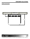
Step 2. Locate the best position for the
UT250-101, but do NOT mount it to the
surface until all the cables are prepared.
Step 3. Prepare the mating cables using
high-quality cables for best results and
durability. Make sure the cables are long
enough to allow for a service-loop and so
the cables can be neatly routed beneath
the table to their destinations.
Step 4. Secure the unit under the table using the
screws provided with the unit.
Step 5. Make all necessary connections to the
UT250-101.
Step 6. When making connections to the terminal
blocks (audio out, control, RS-232, etc.),
use 24-28 AWG stranded wire for best
results. Also, use multi-conductor cable
where possible. For example, a standard
4-conductor cable works well for the
RS-232 connection.
Step 7. Use the cable clamps provided to secure
the cables to the bottom of the table/desk.
Do NOT bend the cables too sharply
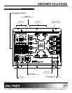
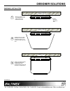
Step 8. Attach the cable support to the
UT250-101 as shown in Diagram 5. This
will help alleviate the strain of the cables
pulling from the connectors and protect
the cables from being accidentally pulled
free or damaged.
Step 9. After power is applied to the UT250-101,
the unit is operational.
OPERATION 7
7.1 MANUAL CONTROL
7.1.1 OUTPUT SELECT CONTROLS
The Output Select Control inputs on the front of
the UT250-101 allow 8 users direct control of
video switching. In this method, each user
typically has a control panel with 2 illuminated
switches along with video and audio inputs.
(See Diagram 6 for details and wiring
information.)
When a user presses a control switch, the video
and audio from that control panel are displayed
at the output of the UT250-101. Each switch
connects its corresponding input to 2 outputs,
either 1A/1B, or 2A/2B. Once the connection is
made, the LED for that switch turns on. If the
switch’s LED is on and the switch is pressed,
the output is disabled and the LED turns off. The
audio output follows the last video input
selected.
7.1.2 AUTO-SWITCH MODE
In Auto-Switch mode, the UT250-101
automatically switches to the lowest input
number with an active signal applied. For
example, if there is a signal on Input 4 and a
new signal is applied to Input 2, the outputs
defined with the Auto-Switch command will
switch to Input 2.
The Output Select Control inputs override
Auto-Switch mode. When a user selects an
input using an external switch, the UT250-101
automatically switches to the selected input.
In Auto-Switch mode, Input 8 is designed for use
as a logo input that displays when the system is
not in use. If Auto-Switch mode is enabled then
overridden by the Output Select Control inputs,
when all active inputs are removed from
Inputs 1-7, the UT250-101 automatically
switches to Input 8.
Auto-Switch mode must be set using the
RS-232 input. See the AUTO commands in the
following section for details.