


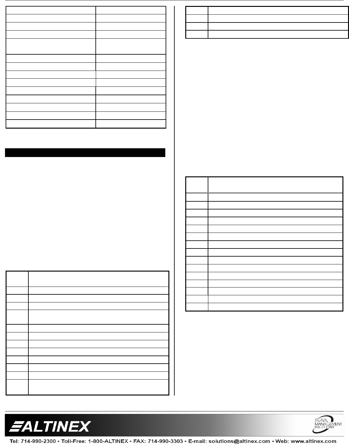
INTERFACES
4
Ohms)
Cross-talk <80dB @ 1 kHz
Signal-to-Noise Ratio >95dB
Bandwidth 10 Hz – 40 kHz
Stereo Channel Separation >75dB @ 1 kHz,
>60dB @ 20 kHz
Frequency Compatibility
Horizontal 15-130 kHz
Vertical 25-180Hz
Minimum Video Bandwidth 350MHz
Horizontal Position Range
20%
Cross-talk
39dB @ 100MHz
Power
Internal Power Supply 90-140/200-240 V
Power Consumption
12 watts max.
Table 3.
VA6831FC
Electrical
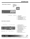
VA6831FC DESCRIPTION 4
4.1 COMPUTER VIDEO INPUT (VGA-
COMPATIBLE 15-PIN HD CONNECTOR)
The two 15-pin HD inputs allow the connections
of two computers to the interface using cables
with a 15-pin HD connector on the interface end
and a matching connector on the computer end.
This 15-pin HD connector allows greater
flexibility and versatility from the
VA6831FC.
All
ID pins are passed through
for proper boot up
mode. Several computers like the PC, MAC,
SUN, and SGI can be attached using the proper
cables as described in Section 8 - Accessories.
PIN
No.
INPUT SIGNALS ON 15-PIN HD FEMALE
CONNECTOR
1
Red Video
2
Green Video
3
Blue Video
4
ID Bit (Connected to Ground when ID Bit switch
is ON)
5
Ground
6
Ground
7
Ground
8
Ground
9
No connection
10
No connection
11
ID Bit
PIN
No.
INPUT SIGNALS ON 15-PIN HD FEMALE
CONNECTOR
12
ID Bit
13
Horizontal Sync/Composite Sync
14
Vertical Sync
15
No connection
Table 4.
VA6831FC
Dual Input pin-outs
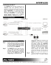
4.2 LOCAL MONITOR OUTPUT (15-PIN HD
CONNECTOR)
Each of the inputs has a local monitor output
through a 15-pin HD female connector. These
outputs allow the connections of a local monitor
up to 12 feet away from the interface.
These are fully buffered outputs, eliminating
reflections often caused by “Y” type monitor
breakout cables. It is not necessary to terminate
the unused output. The output is VGA
compatible, but can also be used to transmit
signals to other types of local monitors using the
provided Altinex
adapter cables such as VGA,
MAC, SUN, SGI, or RGB.
PIN
No.
LOCAL MONITOR OUTPUT SIGNALS ON
15-PIN HD FEMALE CONNECTOR
1
Red Video
2
Green Video
3
Blue Video
4
ID Bit /Grounded when ID Bit switch is ON
5
Ground
6
Ground
7
Ground
8
Ground
9
Composite Sync
10
No connection
11
ID Bit
12
ID Bit
13
Horizontal Sync/Composite Sync
14
Vertical Sync
15
No connection
Table 5. Dual Local Monitor Outputs pin-out