


INTERFACES
7
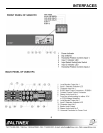
4.8 MOUNTING CAPABILITY
The
VA6831FC
can
be easily mounted into an
equipment rack. Four mounting holes are
provided on each side of the unit. To mount a
single unit, use Altinex 19”-1U Rack Mount Ears
(part
#
DA1294FC
). To mount two units in
tandem, use an Altinex 19”-1U Rack Mount
Shelf (part #
DA1293FC
). For under the table
mounts, optional brackets, such as
TM1271
,
TM1272
,
TM1273,
or
TM1274
can be used.
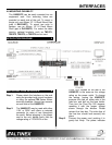
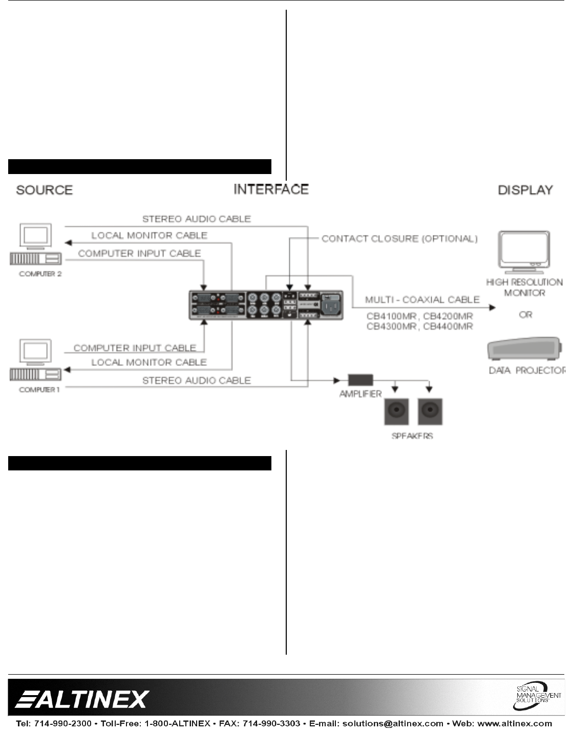
APPLICATION DIAGRAM 5
INSTALLING YOUR INTERFACE 6
Step 1.
Please attach the Interface on the rack
using the provided rack mount hardware
or using the optional
TM
Series Altinex
mounting brackets, through two screens
on each side of the
VA6831FC
.
Step 2.
The
VA6831FC
may be used with either
110V or 220V and offers a universal
connector for ease of use throughout
the world. Before plugging in the power
cord to the unit, please verify that the
voltage rating of 110V/220V on the
FUSE CLIP located
on the rear of the
VA6831FC
is the same as the voltage
rating on the power outlet. To change
the setting, unplug the
VA6831FC
,
squeeze the clips on either side of the
fuse box, and pull out the fuse holder.
Then turn the Fuse Dip 180 degrees,
resetting it with the proper voltage
shown through the window. Please
reinsert the fuse box. The side clips of
the fuse box should lock securely into
place.
Step 3.
Connect the power cord, pushing it in
gently but firmly. The power indicator