


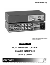
INTERFACES
6
4
.
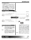
3 MAIN (RGBS/RGBHV) OUTPUT THROUGH 6
BNC CONNECTORS
BNC connectors offer a reliable connection for
high-resolution video signals, and they facilitate
easy cable maintenance in the field. The main
output of the
VA6831FC
is configured with six
BNC connectors. By selecting the appropriate
combinations, these outputs can provide RGsB,
RGBHV, or RGBS output signals. RGsB type
input signals are passed through only because
the
VA6831FC
does not separate SYNC from
the Green signal. With these connectors, the
VA6831FC
can be connected to compatible
projectors using 4-coax cable for RGBS signals
or 5-coax cable for RGBHV signals.
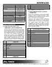
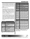
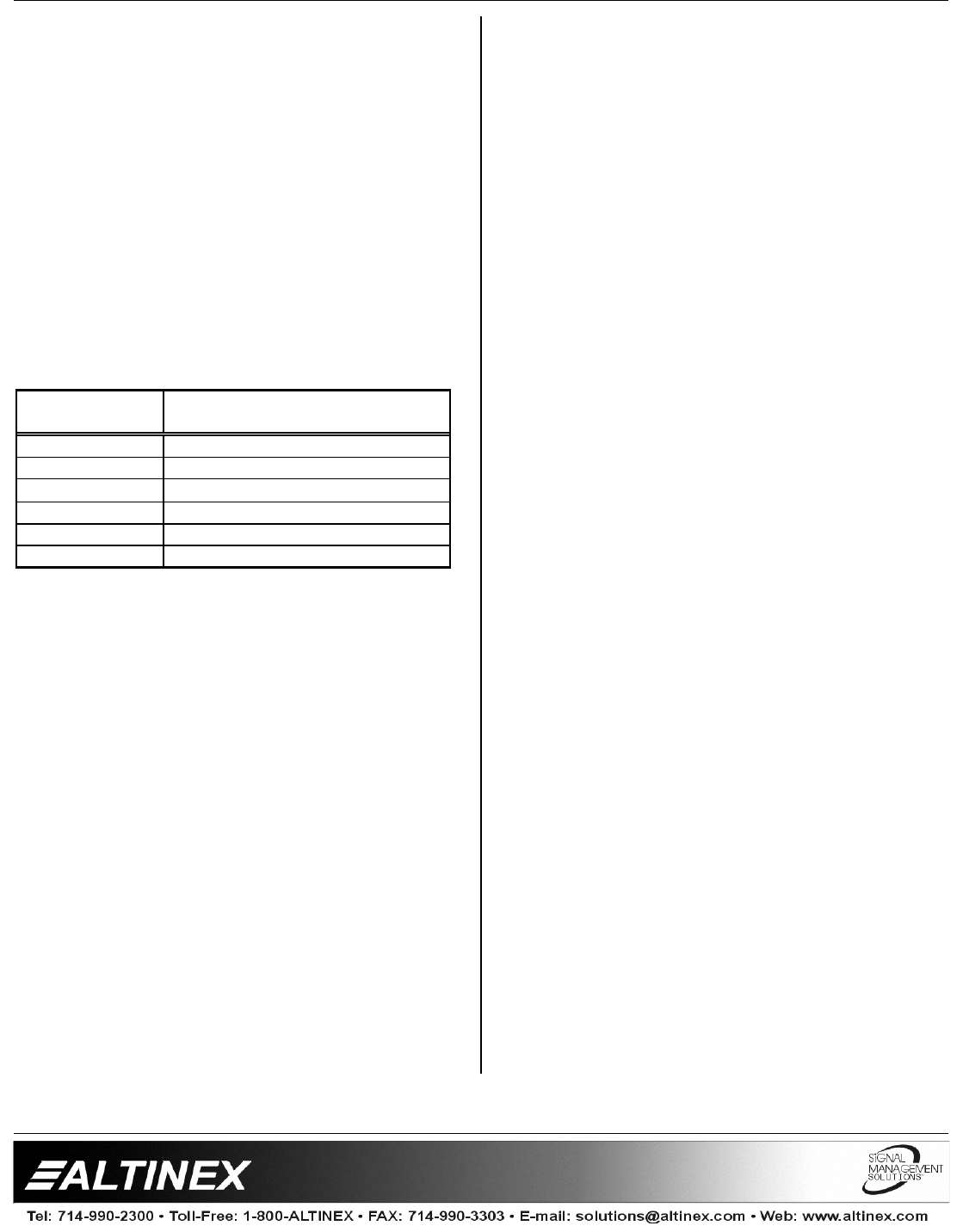
CONNECTOR OUTPUT SIGNALS (6-BNC
FEMALE)
Red
Red Video
Green
Green Video
Blue
Blue Video
Sync
Composite Sync
Horizontal
Horizontal Sync
Vertical
Vertical Sync
Table 6.
VA6831FC
Main Output pin-outs
4.4 INPUT SELECTION SWITCH
The selection of inputs between one and two are
accomplished by using the Input Select Switch
on the front panel. This switch has three
positions: left, center, and right.
By switching to the left, the unit will select
INPUT
1. By switching to the right, the
VA6831FC
will select INPUT 2. The center
position is a REMOTE/AUTO mode.
The LED lights on each side of the Input Select
Switch will indicate which input is selected.
If only one source is present and the Input
Select Switch is in the
VA6831FC’s
AUTO
mode
,
the unit will select the active input. An on
LED will indicate the active input.
When two active sources are present and the
Input Select Switch is on the REMOTE/AUTO
position, the
VA6831FC
selects INPUT 2 as the
default turning LED 2 red.
4.5 HORIZONTAL POSITION ADJUSTMENT
Most monitors and projectors have the ability to
adjust the horizontal position of the image, but
sometimes it is helpful to control this feature at
the interface. This control is especially useful
when multiple computers are switched to a
single display if the Horizontal positions for each
computer is slightly different.
The
VA6831FC
offers a horizontal position
adjustment for each of the inputs. Turning the
Horizontal Position Adjustment knob (blue color)
located on each side of the INPUT SELECTION
SWITCH will set the unit.
First, make sure that the CH1 Horizontal Delay
and CH2 Horizontal Delay dip-switches are OFF.
With the interface Input Select Switch on
REMOTE/AUTO (center position) and the
Horizontal Position Control Switch centered,
adjust the image using the monitor or projector’s
Horizontal image position control. Then set the
Input Select Switch to the desired input and
adjust the Horizontal position of the image on
the display with the
VA6831FC’s
Horizontal
Position Control knob.
4.6 AUDIO
The
VA6831FC
accepts two balanced stereo
audio inputs and offers one unbalanced stereo
audio output. Please note that the audio signal
will follow the video signal during switching,
which means that in either manual selection or
auto-switch mode, if Input 1 is active then both
video and audio signals will be selected for this
input.
4.7 BANDWIDTH
The minimum bandwidth of the
VA6831FC
is
350 MHz, and the typical bandwidth is 425 MHz.
This high bandwidth allows the passing of a
video signal’s third harmonic, thus ensuring a
clean video signal. Indeed, the
VA6831FC
will
be virtually transparent to the video signal.