


INTERFACES
8
light on the front panel of the
VA6831FC
should turn on.
Step 4.
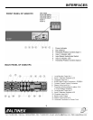
Connect one end of the input cable to
the video output of the computer and
the other end to the 15-pin HD input
connector of the
VA6831FC
. Repeat
this step if two computers are to be
interfaced.
Step 5.
Connect a cable from a local monitor to
the 15-pin HD Local Monitor Output
connector of the interface. Repeat this
step for a second local monitor if two
computers are to be interfaced. It is not
necessary to terminate this output with a
termination plug if a local monitor is not
attached.
Step 6.
Connect one end of an output cable to
the main output’s BNC connectors of
the
VA6831FC
. Connect the other end
to the RGB input on the projector, or
presentation monitor. One can use
either a 4 BNC or 5 BNC coaxial cable
depending on whether the system is
designed as RGBS or RGBHV. Please
note that if the projector has a 15-pin
HD connector, five BNC to 15-pin HD
cables (part
#
MS8102CA
) are available
from Altinex.
Step 7.
Make sure that the dip-switches are
properly set according to Section 7.
Step 8.
Please adjust the Horizontal position of
the image as described in Section 4.5.
If your computer and display device are turned on
and you see a good clear image, you have
successfully interfaced your computer with the
video display.
CONGRATULATIONS! YOU ARE DONE.
OPERATION 7
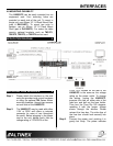
The settings of the
VA6831FC
Interface can be
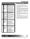
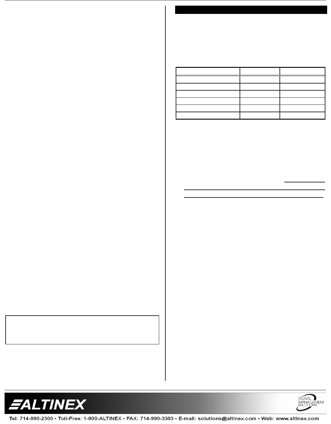
adjusted using the dip-switches in Table 4. There
are no other adjustments necessary to operate the
unit. The
VA6831FC
will operate successfully as
long as the cables are attached properly and
technical specifications are followed.
DIP SWITCH OFF ON
Not Used X
Sync on Green X
Ch1 Horizontal Delay X
Ch2 Horizontal Delay X
ID Bit 1 X
ID Bit 2 X
Table 7. Dip-switch default settings
7.1 SYNC ON GREEN OUTPUT SWITCH
Often systems that use large matrix switchers
are designed to switch signals in RGsB format.
In these types of systems, the ability of the
VA6831FC
to output the Sync signal on the
Green signal can be very useful. It is important
to know that the
VA6831FC
will not separate
Sync from the Green signal if the input is RGsB.
It will simply amplify the RGsB and pass it
through. It will combine the Sync signal with the
Green Video signal when the Sync on Green
dip-switch is in the ON position, regardless of
whether the input sync is RGBS or RGBHV. If
the desired output is RGBS or RGBHV, then
leave the Sync on Green dip-switch in the OFF
position.
7.2 HORIZONTAL DELAY REMOVAL (CH1 &
CH2)
The
VA6831FC
offers the ability to bypass
horizontal
delay.
This may be necessary when
interfacing with projectors or monitors with
sensitive sync inputs, particularly with LCD
projectors. By setting the appropriate dip switch
for Input 1 or Output 2 to the ON position, the
VA6831FC
will output the same type of Sync
signal as is being fed into it from the source. In
this setting, Horizontal position control of the
VA6831FC
is disabled and any adjustments to
the image position must be done at the monitor
or projector. If the CH1 Horizontal Delay dip-
switch is in the OFF position, then the horizontal
If you experience any problems, please call
1-800-258- 4623 or 1-714-990-2300 for
international calls.