


Chapter 11 Pin Descriptions 72
26237C—May 2003 AMD Athlon™ XP Processor Model 10 Data Sheet
Preliminary Information
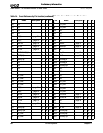
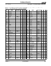
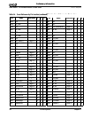
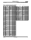
11.3 Detailed Pin Descriptions
The information in this section pertains to Table 24 on page 64.
A20M# Pin A20M# is an input from the system used to simulate address
wrap-around in the 20-bit 8086.
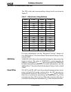
AMD Pin AMD Socket A processors do not implement a pin at location
AH6. All Socket A designs must have a top plate or cover that
blocks this pin location. When the cover plate blocks this
location, a non-AMD part (e.g., PGA370) does not fit into the
socket. However, socket manufacturers are allowed to have a
contact loaded in the AH6 position. Therefore, motherboard
socket design should account for the possibility that a contact
could be loaded in this position.
AMD Athlon™
System Bus Pins
See the AMD Athlon™ and AMD Duron™ System Bus
Specification, order# 21902 for information about the system
bus pins—PROCRDY, PWROK, RESET#, SADDIN[14:2]#,
SADDINCLK#, SADDOUT[14:2]#, SADDOUTCLK#,
SDATA[63:0]#, SDATAINCLK[3:0]#, SDATAINVALID#,
SDATAOUTCLK[3:0]#, SDATAOUTVALID#, SFILLVALID#.
Analog Pin Treat this pin as a NC.
APIC Pins, PICCLK,
PICD[1:0]#
The Advanced Programmable Interrupt Controller (APIC) is a
feature that provides a flexible and expandable means of
delivering interrupts in a system using an AMD processor. The
pins, PICD[1:0], are the bidirectional message-passing signals
used for the APIC and are driven to the Southbridge or a
dedicated I/O APIC. The pin, PICCLK, must be driven with a
valid clock input.
Refer to “VCC_2.5V Generation Circuit” found in the section,
“Motherboard Required Circuits,” of the AMD Athlon™
Processor Motherboard Design Guide, order# 24363 for the
required supporting circuitry.
For more information, see Table 15, “APIC Pin AC and DC
Characteristics,” on page 40.
CLKFWDRST Pin CLKFWDRST resets clock-forward circuitry for both the system
and processor.