


Builder’s Guide for AMD Athlon™ 64 Processor-Based
Desktops and Workstations
31684 Rev. 3.00 September 2004
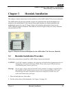
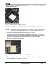
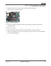
Figure 9. Tightening Down the Retention Frame
10. Lift the socket locking-lever. (Gently pull it away from the socket body, and then lift up.)
Warning: Do not apply voltage until the heatsink is fully installed. If voltage is applied before
the heatsink is fully installed, the processor will overheat and failure will result.
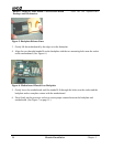
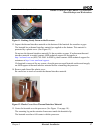
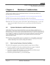
11. Gently place the processor into the zero insertion force (ZIF) socket.
The AMD Athlon 64 processor has a small triangle marking on one corner. (See Figure 10.)
This triangle corresponds to the alignment marking on the motherboard. The corner with the
triangle must be located at the corresponding corner marked on the motherboard.
Be careful not to bend the processor pins.
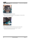
Figure 10. Alignment Markers on Processor and Motherboard
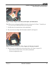
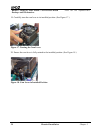
12. Push down gently on the processor while lowering the locking lever and latching it into the
fully locked position. (See Figure 11 on page 17.)
16 Heatsink Installation
Chapter 3