


31684 Rev. 3.00 September 2004
Builder’s Guide for AMD Athlon™ 64 Processor-
Based Desktops and Workstations
List of Figures
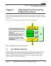
Figure 1. AMD Athlon™ 64 Processor Architecture ........................................................................9
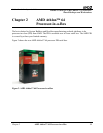
Figure 2. AMD Athlon 64 Processor-in-a-Box................................................................................11
Figure 3. AMD Athlon 64 FX Processor-in-a-Box .........................................................................12
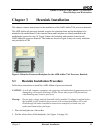
Figure 4. Retention Frame and Backplate for the AMD Athlon 64 Processor Heatsink.................13
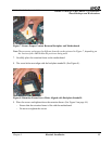
Figure 5. Backplate Release Liner...................................................................................................14
Figure 6. Motherboard Placed Over Backplate................................................................................14
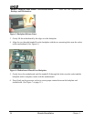
Figure 7. Ensure Proper Contact Between Backplate and Motherboard .........................................15
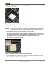
Figure 8. Retention Frame Screw Holes Aligned with Backplate Standoffs...................................15
Figure 9. Tightening Down the Retention Frame ............................................................................16
Figure 10. Alignment Markers on Processor and Motherboard ......................................................16
Figure 11. Pushing Gently Down on the Processor .........................................................................17
Figure 12. Plastic Cover Over Thermal Interface Material .............................................................17
Figure 13. Heatsink Centered Over Processor.................................................................................18
Figure 14. Heatsink Spring Clip ......................................................................................................18
Figure 15. Pushing Straight Down on the Clip................................................................................19
Figure 16. Correctly Installed Spring Clip.......................................................................................19
Figure 17. Turning the Cam Lever ..................................................................................................20
Figure 18. Cam Lever in Installed Position .....................................................................................20
Figure 19. Installed Heatsink ...........................................................................................................21
Figure 20. Desirable Airflow—Power Supply with Bottom Inlet ...................................................25
Figure 21. Undesirable Airflow—Power Supply with Front Inlet Only .........................................25
List of Figures 5